I bought a stepper motor, number 1205 and an A4983 Stepper Motor Driver Carrier with Voltage Regulators. I saw the diagram for the motor and the two diagrams with the labels on them for the driver board. They even have colored lines but I don’t understand them. I’m a real newbie.
Could you please tell me which colored wires from the motor, go to where on the board and if I have wires coming from the Arduino pins, where do they go?
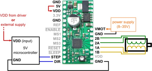
For your stepper motor, the black and green wires make up the ends of one motor coil, and the red and blue wires make up the ends of the other motor coil, so one way to connect it would be:
1A and 1B connect to black and green (which goes to which does not matter)
2A and 2B connect to red and blue
As far as making connections to your Arduino, the simplest scenario requires two I/O lines from the Arduino (you can choose any lines you want), one connected to the motor driver’s STEP pin and the other connected to the DIR pin. Since your Arduino has a built-in regulator and is likely being powered separately, you do not need to connect 5 V (VDD) from the motor driver board to the Arduino, but you do need to make sure they have a common ground (i.e. connect GND from your Arduino to one of the GND pins on the motor driver board). Other than that, you should short the VDD pin to the 5V pin above it as shown in the motor driver’s simple connection diagram:
This powers the board’s logic. You will also need to connect a motor power source to VMOT and GND. Does this make sense?
I also have a Rugged Stepper Motor Sheild for the first axis of my machine. I got some advice to jack teh voltage up to 30V so that it would runn fast enough and if works great. Can I just split the power line and also use a common ground? The two motors will never run at the same time and neither run for very long at a stretch.
Yes, you can generally use the same source to power multiple things in parallel as long as it can deliver the total current that all of the parallel systems will be drawing. You should note that even when a stepper motor is not “running”, if the driver is powered and enabled, the motor will still be drawing the full current (as set by your current limit). In this way, stepper motors are not like DC motors. If your motors don’t need much torque to hold their positions when they’re not moving, you might consider using the enable pin to disable the drivers during these periods.
Yes I intended to turn off the motor between uses but for a different reason. Using the other motor I learn that heat could be a big problem! I found out that it kept building heat even when it was not running.
I will try this tonight so I might need something else but I think that I am go to go. Thank you very much so such quick responses and such clear information.
The motor runs but only about 40 RPM. What am i doing wrong.
I have it hooked to 30V
#include <Stepper.h>

#define motorPin1 24
#define motorPin2 26
#define motorStepsTwo 200                           // Change this to fit the number of steps per revolution for stepper two

Stepper myStepperTwo(motorStepsTwo, motorPin1,motorPin2); // Initialize of the Stepper library:

void setup()
{
  Serial.begin(9600);
  myStepperTwo.setSpeed(300);
}

void loop()
{
       digitalWrite(motorPin1, OUTPUT);
       digitalWrite(motorPin2, OUTPUT);
       myStepperTwo.step(100);                      // Drop feeding tube carriage downn into tower openning
}
I was using the A4983. When I increase the speed setting above 300,(myStepperTwo.setSpeed(300) the motor gives off a high pitched sound and doesn’t move. When I lower the number down to 10, it is very slow. As I changing the number higher I gets a predicable progression to faster speeds but it won’t go beyond 300.
I hooked the board directly to the power supply and took the other motor shield off of the Arduino to get it out of the equation. When I did that, the motor shaft turned back and forth, jumping around pretty fast but not turning. I hooked up the VDD and GRD wires to the Arduino like in the diagram and it smoothed back out…even better than before. I still had the same limit. By the way, I have the same max speed of 300 on the other motor with the other shield.
It sounds like you were making changes to your connections with power applied, which is generally a very bad idea. I strongly suggest you always disconnect power before making changes to your wiring.
Do you have your stepper motor output shaft connected to a load? Can you describe how you set the current limit on your A4983 driver carrier?
There could also be a problem with your code (I can’t see what signals its outputting because that’s hidden within the library you’re using). What Arduino pin are you connecting to STEP and which are you connecting to DIR?
Just to be clear, are you saying that you have a second stepper motor that will also go no faster than 40 RPM when connected to your stepper driver shield when using the same code? What are you using for your second stepper motor?
I do turn off the power when I’m going to make changes. I don’t have the shaft under load, just a piece of tape on it like a little flag. I didn’t play with the limiter. I guess that I will. I change the pins to 31 and 33, then 33 and 31.
I had a max call out of 300 on the other motor and stepper driver but the other motor actually turned pretty fast. It is just a bit of a coincident that the limit on this set up has a limit of 300 though.
I hooked up the 1205 motor the rugged shield and (with some tweaking) it runs fast a smooth. Now I will hook the 1205 back to the A4983 and start playing with the current limiter. Good thought. Thanks
I don’t really understand a lot of what you’re asking (e.g. the four-pin configuration question), and you seem to be leaving out a lot of detail while not fully answering my questions, which prevents me from having a clear enough picture of your setup to be able to give you much help.
The 1205 stepper motor does have 200 full steps per revolution, but the A4983 driver supports microstepping. Are you doing anything with the microstepping pins (MS1, MS2, and MS3)? If you leave them all disconnected, the default behavior should be full-step mode (assuming you have version 1202–carrier with regulators–and not 1201).
I left out some of the relevant details because I don’t know enough to ask correctly. Thank you for being patient.
I have seen that with some set ups there is a use of 4 pins instead of two. That is about all that I know.
I am not doing anything with the MS1, MS2 and MS3. I looked at my invoice and I have a 1205 motor and a 1202 carrier.
I tried to set the system up just like your diagram. I jumped the 5V to VDD like it is called out at the top of the graphic and I included the two lines that go from VDD and GND to the microcontroller at the bottom of the graphic. I have the 30V going to the VMOT and GND. I have the black going to 1a, green to 1B, red to 2A and blue to 2B. I have STEP going to 22 and DIR to 24.
I got it working. I went looking through the forum posts and saw your PDF. https://forum.pololu.com/download/file.php?id=487 I added a third line from the Enable terminal on the board to an open pin. I edited the code only to change the pin call outs from 2, 3 and 4 to 22, 24 and 26.
The motor rotates at a good rate and is smooth and steady.
I’m glad to hear you got it working. However, I do not believe the enable pin is responsible for the change in behavior. What happens if you run that same code with the enable pin disconnected?
Please keep in mind, the best I have achieve today is to make two LEDS blink at different intervals - hooking up the stepper motor + a4983 W/R and the Arduino UNO on the breadboard seem impossible to me right now.
I would really appreacite some help on this
Good to see that this threads problem was solved so well!

 the motor gives off a high pitched sound and doesn’t move. When I lower the number down to 10, it is very slow. As I changing the number higher I gets a predicable progression to faster speeds but it won’t go beyond 300.