I was doing some set up testing on the Arduino Mega 2560 with an LCD board on top. I hooked up the VDD wire, which is the next to the bottom pin on the right, to the 5 Volt pin socket on the LCD. It ran fine the first few times but between tests, the VDD wire came off.
I had the VMOT, at 12 volts, off when I hooked it back up. When I did, the LCD shut down. The display stopped right away but it took about 5 seconds for the back lighting to go dark. When I pulled to wire back out, the display came back on and was apparently un-harmed. I plugged it in and pulled it out over and over and got the same shut down response and recovery.
Then I decided to plug the VDD wire into the 5 volt socket at the end of the Arduino board next to pin 22. I got the same issue and I can’t figure out what is going on? Of course the motor won’t work with the VDD wire in or out.
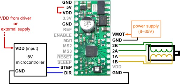
Are you using the A4988 carrier with voltage regulators, and do you have its 5V pin (at the top left) tied to VDD as shown in the diagram you posted? If so, you should not connect the other VDD pin to your Arduino’s 5V pin.
VDD for the A4988 should be supplied from one and only one source, whether that is the onboard regulator or an external regulated source. The connections in the diagram show the A4988 getting VDD from its onboard 5 V regulator, and supplying the same 5 V to the microcontroller (hence the arrowhead on the red wire going into the microcontroller). However, the Arduino has its own built-in regulators, and its 5V pin is an output, so if you connect the A4988 VDD to both its own 5V and the Arduino 5V, you are effectively shorting two voltage supplies together.
If this is not the problem in your case, could you please post a picture or diagram of your specific setup showing how you have everything connected?
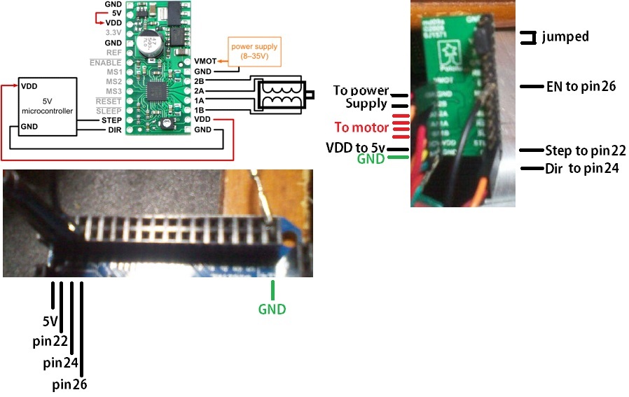
I think that I have it hooked up just like this graphic. I have checked it several times. Of course my next step would be to check all connections…for the third time.
The Arduino does not have a VDD input, so I am not sure what you mean when you say “I have it hooked up just like this graphic”. How are you powering your Arduino? What, if anything, did you connect the lower right VDD pin on the stepper driver to on your Arduino? Do you have the upper left VDD pin on the driver connected to the 5V pin on the driver?
Unfortunately, your picture is too small and dark for me to be able to make out much. Could you try taking closeups of the driver and the connections on the Arduino separately with better lighting?
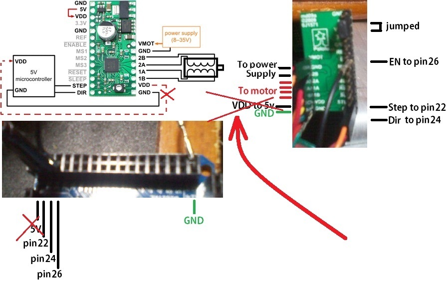
As I mentioned, you should not have both the 5V-VDD jumper and the other VDD pin connected to 5 V on your Arduino. If you remove one of these connections, does your setup work properly?
It sounds like the stepper driver might be damaged, probably in a way that shorts VDD to ground. It is likely this happened either as a result of improper connections or because your loose VDD wire brushed against and shorted to something (since you mentioned it stopped working after your VDD wire came off).
If you contact us directly with your order information and mention this thread, we might be able to at least offer you a discount on a replacement. However, before you try another board, you should make sure you understand how you were connecting the driver’s VDD to two different 5 V sources at the same time and why that is bad for it.