Two 36v4 drivers and two stepper motors

First off, I am very new to the world of steppers.
I have an arduino v3, two 36v4 Pololu stepper drivers and two Pololu #1478 stepper motors.

So far, starting with the example sketch in the Pololu 36v4 stepper library, I have been able to successfully wire-up one motor, power supply, driver and Uno. And to modify the code to change speed, direction and etc. as I wish.
The wiring was per TABLE 1.

Next I want to add the second driver and motor to my project. For this project, I need two motors, ( x and y axis ), two drivers and the arduino uno. For the end result, the motors will operate one at a time - at no time in the sketch will i need to operate both motors at the same time, nor will I need to change speed.
So I think I can wire them up per TABLE 2.

From Driver #2, I will only have 2 wires going directly to the Uno. (to address direction and distance) All the other wires ( ** ) will be spliced into the sister wire going from driver #1 to the uno.

Does this look like it will work if i wire it up ???

Thank you,
Dave

Hello, Dave.

Thank you for the clean tables showing how you are planning to connect everything. You should connect the SCS (SPI chip select) pins on the drivers to different Arduino pins so that the Arduino can communicate with each driver individually. Otherwise, your connections look fine.

- Patrick

PatrickM,
Thanks for reviewing the tables and your suggested change.
Below is the corrected Table 2.

PatrickM,

Dave C

That seems like it should be fine now. Good luck with your project!

- Patrick

Hi Dave,

I am trying to do a similar thing to you, and I have the same wiring ocnfiguration. My first attempt using two 36v4 drivers didn’t work and the second motor got very hot. I was pointed in the direction of chip selecting with the SCS pin.

This is where I saw this post, I have given this a go to no avail yet and wondered how you coded the two separate sd.chipselectpin().

Thanks in advance, Ben

Hi Ben,
Sorry I can not be much help yet. After my last post I did wire things up per the tables and everything seemed fine.
So I downloaded a test sketch that would run one motor and driver. Then things went downhill. I burned up one of the 36v4 drivers. ( I am quite sure this was do to using a breadboard and other poor connections ). Because, I did all rewiring and soldered connections and it worked. But then my NEMA 23 notorious got very very hot before I shut things down.
So then I have put the project aside for now. I need to get back to it soon.
Bottom line, I can’t be much help yet. But I am quite sure it will work.
Good luck,
Dave

Thanks for your quick reply Dave,

Thats a shame, I also wired things up and the motor that was previously getting hot no longer seems to, im just unable to send it the commands I would like. I’m going to try posting in the main fourm.

I hope you get some time to get back to it!

Hello, Ben and Dave.

In case it helps, I wrote an Arduino sketch that uses our library for the 36v4 to control two drivers. Unfortunately though, I am not able to verify it works myself because I am working from home due to the COVID-19 outbreak, and I do not have the required equipment with me. With that in mind, be cautious testing this example for the first time (e.g. use a low supply voltage, monitor motor temps carefully and be ready to disconnect power, etc.), and please let me know if you come across any problems with it.

Also, always check the current limits in the sketch. My code and the examples in our library set the current limit to 1A to avoid burning up the driver, but that could still potentially damage smaller stepper motors.

By the way, before trying to control two drivers, I recommend using our example in the library to confirm that each of your drivers and motors works individually if possible.

// This example shows basic use of two Pololu High Power Stepper Motor Drivers
// using the Arduino library for the Pololu High-Power Stepper Motor Driver.
//
// It shows how to initialize the drivers, configure various settings, and enable
// the drivers.  It shows how to send pulses to the STEP pins to step the motors
// and how to switch directions using the DIR pins.
//
// Before using this example, be sure to change the setCurrentMilliamps36v4 lines
// to have an appropriate current limit for your system.  Also, see this
// library's documentation for information about how to connect the driver:
//   http://pololu.github.io/high-power-stepper-driver

#include <SPI.h>
#include <HighPowerStepperDriver.h>
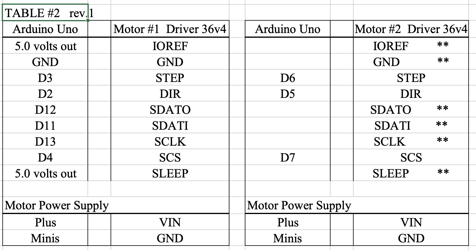
// Driver 1 pins 
const uint8_t sd1DirPin = 2;
const uint8_t sd1StepPin = 3;
const uint8_t sd1CSPin = 4;

// Driver 2 pins 
const uint8_t sd2DirPin = 5;
const uint8_t sd2StepPin = 6;
const uint8_t sd2CSPin = 7;

// This period is the length of the delay between steps, which controls the
// stepper motor's speed.  You can increase the delay to make the stepper motor
// go slower.  If you decrease the delay, the stepper motor will go faster, but
// there is a limit to how fast it can go before it starts missing steps.
const uint16_t StepPeriodUs = 2000;

// Driver 1 object
HighPowerStepperDriver sd1;

// Driver 2 object
HighPowerStepperDriver sd2;

void setup()
{
  SPI.begin();
  sd1.setChipSelectPin(sd1CSPin);
  sd2.setChipSelectPin(sd2CSPin);

  // Drive the STEP and DIR pins low initially.
  pinMode(sd1StepPin, OUTPUT);
  digitalWrite(sd1StepPin, LOW);
  pinMode(sd1DirPin, OUTPUT);
  digitalWrite(sd1DirPin, LOW);
  pinMode(sd2StepPin, OUTPUT);
  digitalWrite(sd2StepPin, LOW);
  pinMode(sd2DirPin, OUTPUT);
  digitalWrite(sd2DirPin, LOW);

  // Give the drivers some time to power up.
  delay(1);

  // Reset the drivers to their default settings and clear latched
  // status conditions.
  sd1.resetSettings();
  sd1.clearStatus();
  sd2.resetSettings();
  sd2.clearStatus();

  // Select auto mixed decay.  TI's DRV8711 documentation recommends this mode
  // for most applications, and we find that it usually works well.
  sd1.setDecayMode(HPSDDecayMode::AutoMixed);
  sd2.setDecayMode(HPSDDecayMode::AutoMixed);

  // Set the current limit. You should change the number here to an appropriate
  // value for your particular system.
  sd1.setCurrentMilliamps36v4(1000);
  sd2.setCurrentMilliamps36v4(1000);

  // Set the number of microsteps that correspond to one full step.
  sd1.setStepMode(HPSDStepMode::MicroStep32);
  sd2.setStepMode(HPSDStepMode::MicroStep32);

  // Enable the motor outputs.
  sd1.enableDriver();
  sd2.enableDriver();
}

void loop()
{
  // Step motor 1 in the default direction 1000 times.
  sd1SetDirection(0);
  for(unsigned int x = 0; x < 1000; x++)
  {
    sd1Step();
    delayMicroseconds(StepPeriodUs);
  }

  // Wait for 300 ms.
  delay(300);

  // Step motor 1 in the other direction 1000 times.
  sd1SetDirection(1);
  for(unsigned int x = 0; x < 1000; x++)
  {
    sd1Step();
    delayMicroseconds(StepPeriodUs);
  }

  // Wait for 300 ms.
  delay(300);

  // Step motor 2 in the default direction 1000 times.
  sd2SetDirection(0);
  for(unsigned int x = 0; x < 1000; x++)
  {
    sd2Step();
    delayMicroseconds(StepPeriodUs);
  }

  // Wait for 300 ms.
  delay(300);

  // Step motor 2 in the other direction 1000 times.
  sd2SetDirection(1);
  for(unsigned int x = 0; x < 1000; x++)
  {
    sd2Step();
    delayMicroseconds(StepPeriodUs);
  }

  // Wait for 300 ms.
  delay(300);
}

// Sends a pulse on the driver 1 STEP pin to tell the driver to take one 
// step.
void sd1Step()
{
  // The STEP minimum high pulse width is 1.9 microseconds.
  digitalWrite(sd1StepPin, HIGH);
  delayMicroseconds(3);
  digitalWrite(sd1StepPin, LOW);
  delayMicroseconds(3);
}

// Writes a high or low value to the driver 1 direction pin to specify what 
// direction to turn motor 1.
void sd1SetDirection(bool dir)
{
  // The STEP pin must not change for at least 200 nanoseconds before and after
  // changing the DIR pin.
  delayMicroseconds(1);
  digitalWrite(sd1DirPin, dir);
  delayMicroseconds(1);
}

// Sends a pulse on the driver 2 STEP pin to tell the driver to take one 
// step.
void sd2Step()
{
  // The STEP minimum high pulse width is 1.9 microseconds.
  digitalWrite(sd2StepPin, HIGH);
  delayMicroseconds(3);
  digitalWrite(sd2StepPin, LOW);
  delayMicroseconds(3);
}

// Writes a high or low value to the driver 2 direction pin to specify what 
// direction to turn motor 2.
void sd2SetDirection(bool dir)
{
  // The STEP pin must not change for at least 200 nanoseconds before and after
  // changing the DIR pin.
  delayMicroseconds(1);
  digitalWrite(sd2DirPin, dir);
  delayMicroseconds(1);
}

BasicSteppingWith2Motors.ino (4.8 KB)

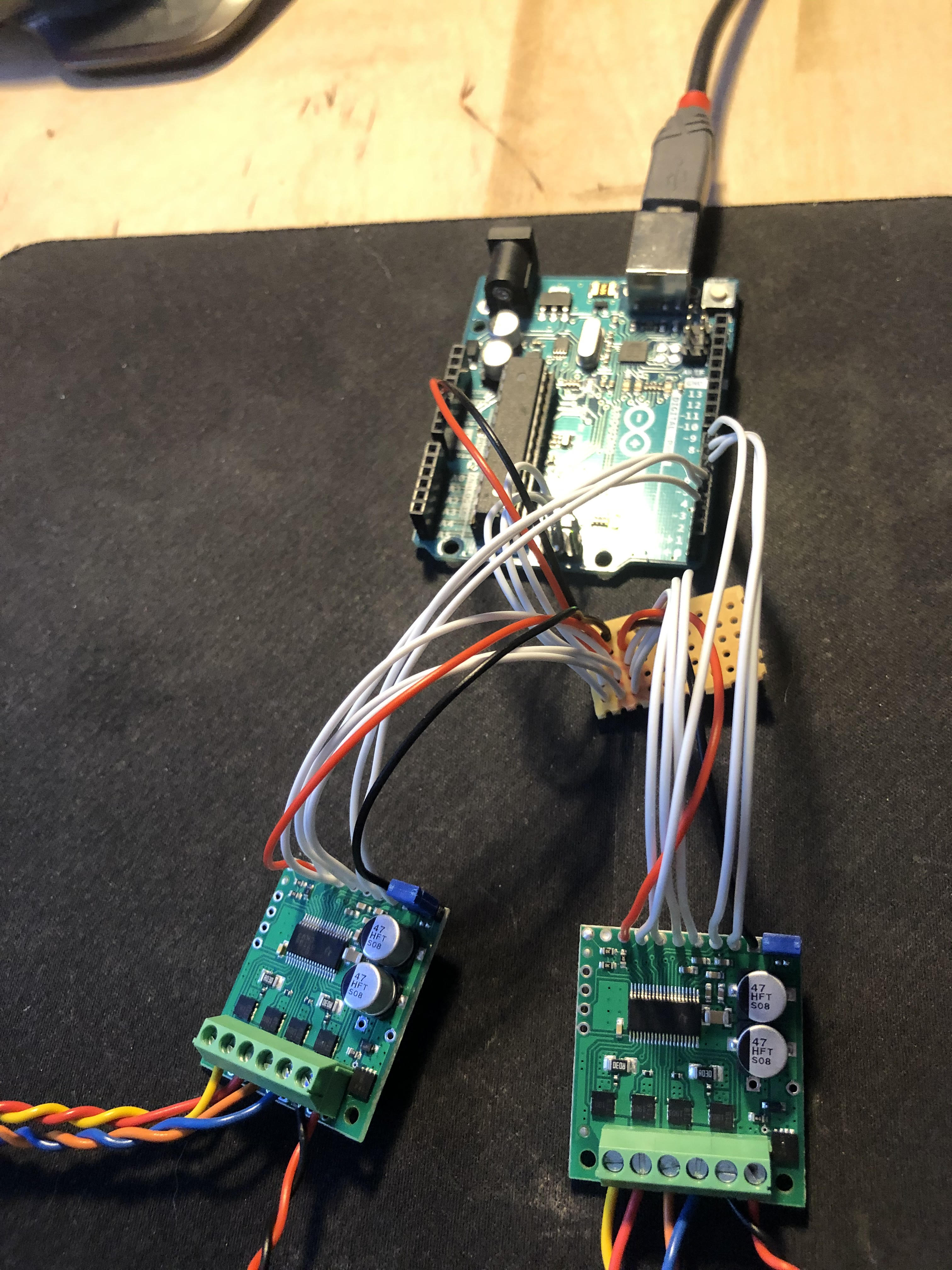
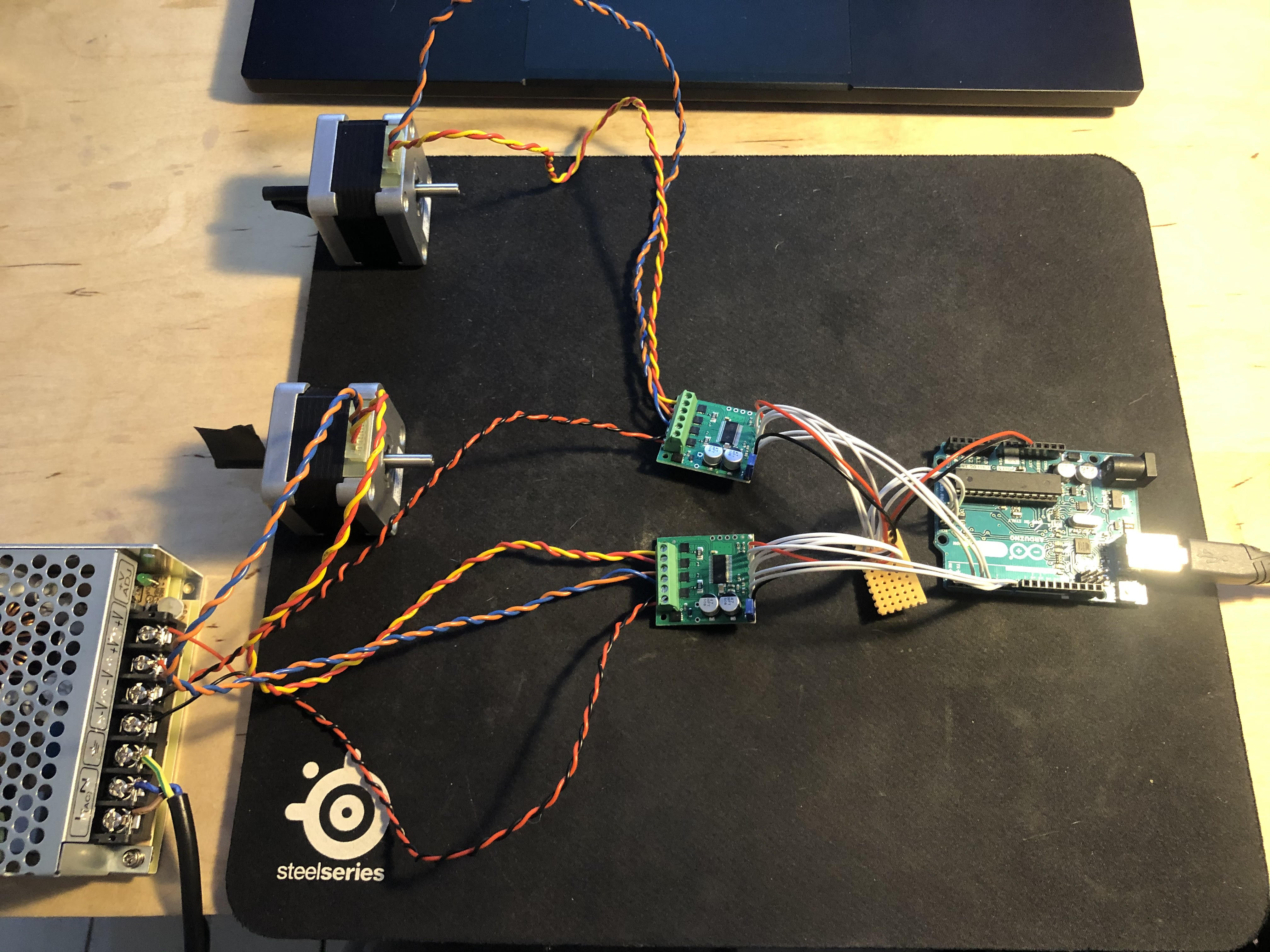
Update: I was able to confirm this program works in a setup with an Arduino Uno wired according to the table in Dave_c’s second post.

- Patrick

Hi Patrick,

Thanks for this, really appreciate the help! Some strange, varying results from testing that code.

First time round the second motor didn’t heat up which I thought was good news as it seemed the current limiting worked. The 1st motor turned as expected but the second did not. They both made a slight noise when the 2nd motor was supposed to be turning but nothing moved. Then the loop ran and the 1st motor turned again, so on and so fourth.

I unpulgged, went over my wiring and pin no.'s etc, everything seemed okay so I tried again. This time the 2nd motor made a high pitched whining noise and heated up while the 1st motor ran its cycles succesfully. Then the 2nd motor tried to turn, the whining sound pitched up while this happened, but it didn’t move. Then I unplugged.

I have tested both drivers and both motors individually whilst set up in the wiring configuration I have now.

Hope this description helps you debug without any of the equipment on you, which cant be easy haha!

Thanks again, Ben

Just to clarify, what was the result when you tested both drivers and motors individually? Can you post some pictures of your test setup with your two drivers and stepper motors connected and take a look at what is going on with an oscilloscope if you have one available?

- Patrick

Hi Patrick,

I have tested to check that both the motors and drivers work when there is no other motor or driver in the circuit and they both do. I don’t have an oscilloscope to test unfortunately, one day!

However when testing with both motors and drivers in the circuit, the 1st motor always works as expected, but the 2nd motor whines, then when it hits the section where it should turn, the whining seems to stop, and the shaft does tiny movements that arent coded, the 2nd motor it is heating up while this is happening so I unplug.

When I remove the 24V power from the 1st driver (all other SPI and digital connections remain in the circuit) the 2nd motor whines, then when the loop hits the section where it should turn, the whining changes tone, but it doesnt produce the tiny movements like before. Again the 2nd motor heating up here so I unplug.

Thankfully nothing has burnt out yet! :slight_smile:

Here are a couple photos of my setup - as i mentioned, using the same wiring as Dave. The stipboard is allowing me to use the same ground, ref voltage and MISO, MOSI and SCK pins.

I would like to try to establish if the problem follows the motor, driver, or Arduino pins. First, can you try switching which motor is connected to each driver to see if the problem follows the motor? Then, can you try switching the wires connected to your Arduino’s pins 2, 3, and 4 with the wires connected to pins 5, 6, and 7 respectively?

By the way, you can get a decent scope these days for a few hundred dollars, so I would strongly recommend investing in one, especially since it sounds like you have already thought about it before. It will save you a lot of time and give you better understanding of your systems, which enables better designs, better margins of operation, etc. Without one, you’re left mostly just guessing about what might be happening, which is not a great way to operate.

- Patrick

Hi Patrick, thanks for your consistent help so far! I will have a look at getting a scope, I can see how one would be very useful. With regards to debugging:

When I switch the motors, the problem stays with the driver,
When I switch the driver pins, the problem switches with them.

So it seems that whichever driver is on pins 5, 6 and 7, is where the problem occurs regardless of the motor connected to it. The step pin always seems to be sending the step signal to the driver in question as when the loop reaches the 2nd driver step function, the motors behaviour changes.

Ben

Patrick,

Is there a Pololu product that would be easier for me to accomplish this task with? I am eventually hoping to control six motors from the same arduino?

That is interesting. Could you try switching which pins correspond to each driver in your code and tell me what happens? Basically, replace

// Driver 1 pins 
const uint8_t sd1DirPin = 2;
const uint8_t sd1StepPin = 3;
const uint8_t sd1CSPin = 4;

// Driver 2 pins 
const uint8_t sd2DirPin = 5;
const uint8_t sd2StepPin = 6;
const uint8_t sd2CSPin = 7;

with

// Driver 1 pins 
const uint8_t sd1DirPin = 5;
const uint8_t sd1StepPin = 6;
const uint8_t sd1CSPin = 7;

// Driver 2 pins 
const uint8_t sd2DirPin = 2;
const uint8_t sd2StepPin = 3;
const uint8_t sd2CSPin = 4;

If you want to control a lot of stepper motors, it would probably be easier to do that using our Tic stepper motor controllers. The Tics offer a variety of control interfaces, and the Tic 36v4 is based on the same driver used on our High Power Stepper Motor Driver 36v4. They can be daisy chained if you use the TTL serial or I2C interface, and we have an Arduino library as well as example codes in the user’s guide.

- Patrick

Hey, i’m new in this forum and also tried to use the same configuration to Control to stepper motors.

I tried your last tip, but without any success. What would be the next step to get this configuration working?

Best regards
Matthias

Hello, Matthias.

Can you elaborate on what is going on with your setup and post some pictures of it? Are you experiencing the same exact behavior BenJSharman described, where one stepper motor will consistently not run and the issue appears to follow whatever is connected to pins 5, 6, and 7?

- Patrick

Hi Patrick,

Have you been able to confirm that running two 36v4 stepper drivers from one Arduino does work as intended? I’m starting out on a design at the moment, and it’d be great if I could get some indication on whether I’m heading down the right path, or would need some firmware slog in order to make it work properly.

Thanks!

Hello, bienvenu.

Yes, I did confirm that the program I posted earlier works for controlling two of our High-Power Stepper Motor Drivers with an Arduino Uno, so if you wire your setup according to Dave_c’s second post and set the current limits in the code appropriately for your stepper motors, it should work.

- Patrick