Hello everybody. I am having trouble interpreting the raw magnetic readings from the MinIMU-9 v2 Gyro, Accelerometer, and Compass (L3GD20 and LSM303DLHC Carrier). I am capturing the data using 8051 and the sample code for the capture data in my function is
When i plot the x,y,z data in excel, i get a spherical shape which indicates to to me that its good.
But, when i rotate the device around the Z- axis, the Y value does not change much at all, the Y value seems to change much when rotated about the Y axis. I have attached a word document file of the readings I am getting.
Why would the Y values not change much when rotating about the Z axis and change about the Y ? Please help, I hope the docx document will be visible.
Thanks everyone Mag readings.docx (44.2 KB)
Your problem is just that you are confusing the Y and Z axes. If you look at the LSM303DLHC datasheet, you can see that the magnetometer registers are ordered: X, Z, and Y. Everything should be fixed if you change your code to:
Wow, i did not notice that. I guess i went by the conventional order x,y,z and overlooked the x,z,y order.
Thank you for pointing out my error. I will be correcting that and will post the developments or incase i have any issues. Thank you very much Ben
One other thing, i read in one of the forums that when the device is pointing north, the X should be “semi-max” and Y–(in my case Z) should be near 0 ,Given that i switch the y and z values. That is not what i am observing when i look at the data i posted. Also it seemed that when the device is pointing south and west the only axis that seems to change considerably is the X axis value. Is this an issue ?
What is your geographic location? Are you holding the board near anything that could be affecting the local magnetic field, such as close to a desk? Can you try rotating the board around the Z axis and post a plot of the X and Y values?
My board is mounted on breadboard that is on top of a table. The computer is about 1 foot away from the board. I am located in Fort Wayne IN, is that the answer for your geographic location ? I have attached a text file of my data reading when rotating my breadboard around the z axis of the module. One thing i noticed too is that all the x and y values are negative. X seem to have both negative and positive values only if i rotate the module about the Y axis and same thing to Y value changing both negative and positive if rotated about the X axis.
I have attached graph for x,y when rotating around the z axis. I started out pointing x axis approximately geographic north then rotated the board clockwise a whole 360+ degrees. Total about 400 degrees.
Thank You compassread.txt (6.28 KB) Mag readings.docx (44.2 KB)
I don’t see any graph in the two files you attached. Am I missing something, or did you attach the wrong file?
I graphed the data you provided in compassread.txt and it looks like something strange is going on. That all of your magnetometer readings are negative also makes it seem like there are some pretty big distortions in the local magnetic field. Can you try getting data with your compass at least several feet away from anything that might be interfering, such as your table and computer?
Sorry i might have attached the wrong graph. I attached the right one. My concern is, is the device that extra sensitive that objects will throw off its readings. My main application will be to mount it on a robot so to control the direction of the robot more accurately. Will it work since stuff like motors will be around a foot radius and may induce magnetic fields.
I will try what you suggested and post the results.
Thank you Doc1graph.docx (32.2 KB)
Ok, that graph is what I got when I plotted the data you attached in your previous post, and it is not a circle like I would expect. I am not sure exactly what is going wrong, but as I said before, I suspect something in the environment is at least intermittently interfering, and you should be able to verify that or rule it out by seeing what happens if you change your environment.
Keep in mind that this board is just measuring the local magnetic field. The problem is not that this particular device is extra sensitive, it is that something in the environment is producing a field that overwhelms the Earth’s magnetic field, and any compass/magnetometer in that location will produce the same erroneous results. If there is a lot of magnetic noise from your robot, you might need to mount the compass on a mast in order to get decent results (or you might be able to calibrate the compass once you mount it on the robot to compensate for the field distortions).
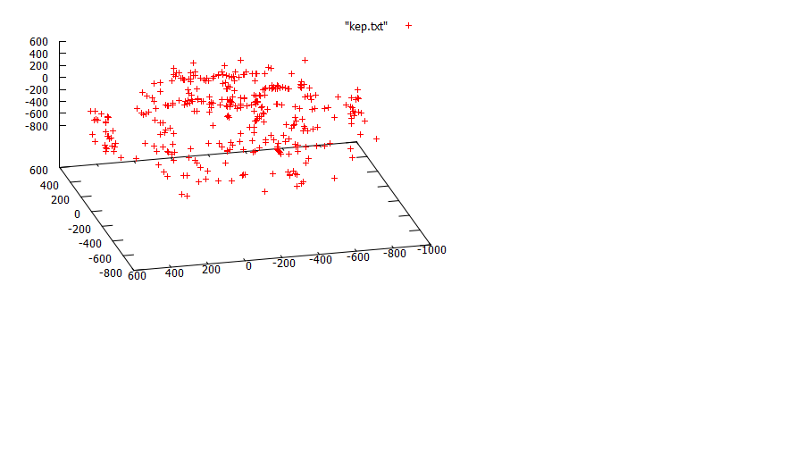
I changed my location and took the chip off the breadboard and rotated it while holding it. I got some data points that looks better but I am not sure about the X Y though i see it looks better. I have attached a word document with both the data points and the graphs for X Y values when the board is rotated about the Z axis and for all the axis X Y Z when i do a complete rotation. Does the data make sense ? CURRENT DATA.docx (83.6 KB)
Your XY plot data looks strangely discontinuous. If you are rotating it at a reasonable speed and reading the data rapidly, I would not expect to see discontinuities like that. Can you post the full code you are using?
Separately, you should be able to do some tests to better understand what is happening. You should see a circle (or at least an ellipse) when you plot the data as an XY scatter when rotating about the Z axis. If this isn’t what you’re getting, try to figure out why. For example, leave the board stationary for ten seconds and plot the data you get. Does it jump around or is it all concentrated at approximately the same location? Turn the board to a new orientation and do the same thing. Repeat this for the four cardinal directions, then try adding some intermediate points. This process will either slowly create a circle, or it will give you a better understanding of where things might be getting weird. Basically, try to simplify what you’re doing.
when i leave my board at a stationary position, the data seems to be approximately the same +/- 3… Example, at a point i will get
X Y
-122 -207
-122 -211
-121 -210
This will happen for all points i test, the values will be approximately around the same range.
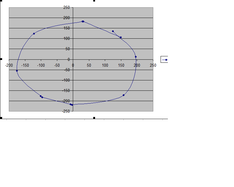
I decided to draw a circle and divide it 8 times, i.e 45 degrees segments. I placed my compass in the middle and started at a marked point “0 degrees”, rotated my board 360 degrees clockwise with 45 degrees increments , then repeated the process with 90 degrees increment and recorded the data. The 90 degrees increment-4 data points- gave me a near perfect circle. The 45 degrees increment did not at all as shown by the graphs. Somehow around 45 degrees, 135 degress, 225 and 315 my points jumps as though the board is tilted or something. For instance my values with linearly increase/decrease and suddenly to a much higher value or much lower value then increase/decrease linearly. It does this in a pattern and it is consistent too, can the board be defective ?
NOTE: I am using SMBus communication which i believe should be compatible with the I2C protocol. degrees increaments data.docx (39.1 KB)
I have attached another word document with more details to what i am observing. The board is flat on the x-y plane and being rotated about the Z axis clockwise. There is a smooth transition of both the X and Y raw values for the most part but also some big jumps. e.g X will decrease normally from 50, 48,47…4,3,2,0 then at 0 there it will jump to like -259 then progress smoothly -259,-263,-270…up to a min of about -385 then jumps depending on how the Y values behave too…
I have explained it in the word document.
NOTE:
My Z values ranged from 229 to 233 during the entire 360 degree rotation of this process.
I did not record all data points that seemed to have a smooth transition, I mainly recorded the jumps and noted them, so the data that is not noted there was a good long transition. This seems to happen all the time i calibrate. The unusual behavior is consistent hence i am wondering if the board is defective…
The 3d plot is when i do a full rotation(3d)
Thank You.
I took the time to go through my code thoroughly and realized i actually had a mistake that i overlooked.
for(play=0;play<8;play++)
{
in_buffM[play]=ByteRead(MAGNET,MR_REG_M+play); //MAGNET=0X3C
}
My mistake was I initialized my “in_buffM[8]” as a “char”. So everytime the value exceeds 255 it resets to zero when i am doing the shifting by 8 bits. I changed it to “int long” and now my results have improved. Now i will proceed and do the full calibration, scaling and try to get degrees values.
Thanks a lot Ben for your assistance and your recommendation to go through the code again.