VL53L0X -- maximum sensors on I2C arduino bus

Hi, Andrei.

Thanks for the details about your setup. As you might have seen from the GitHub issue you posted on, there seems to be something different between the Pololu VL53L0X boards and the ST satellite boards, so it would be interesting to see if our boards work in your setup.

The level shifters in the satellite boards are supposed to have built-in pull-up resistors, but I don’t know how well those work. It’s hard to tell from your pictures, but do you have any external pull-ups on the I2C signals? If not, could you try adding some to see if they make any difference? 4.7k or 10k might be good values to start with; if you have an oscilloscope, that could be useful to see what effect they have.

Can you tell at what point the code freezes?

Kevin

Hi Kevin,

Thank you for the help and hints.
There was no code freeze, rather a bus freeze - the bus would stop working. This needed a sensor reset to fix it - a simple micro reset would not work.

Got the Pololu units last night - 8 sensors working on the bus, no delays in code and some “even more horrible” wiring - long cables, breadbard to breadboard etc.

It runs very very well and stable. I am now testing long term stability, noise and bus freeze issues. Will be running the setup for a few hours today and checking/logging.
Seems all boils down to the level shifters ST used in the Satellite boards. Once those are out of the equation all runs very smooth.

As pullup resistors I tried 1k, 2k, 4k7 - all seems to work well.

My only issue with the boards is the fact that not all pins are level shifted (Especially the XSHUT, which is always driven when 2 sensors are needed). I know they should work even without this but for peace of mind it would have been ideal to protect all the pins :smiley:

Overall the performance seems fine. Will update if I come across any strange behaviour.

2 Likes

Good to hear you got it working with our boards. We’d be interested to hear what you find out from your continued testing.

By the way, our carrier boards have onboard pull-up resistors, so you shouldn’t need external pull-ups, though adding them shouldn’t be a problem either.

Kevin

Hello people

I have an urgency.

I change the address via Github library, in order to have a unique address from these sensors and I have no Idea, why the address changes back after power cut off

Hello, Oleglyan.

We noticed you posted more questions about this in another topic and we felt it was best addressed there:

-Nathan

Here is my ArduinoCode I used with ProMini and Nano

I could have saved my time by reading this earlier, which should be highlighted I suppose:
The sensor’s 7-bit slave address defaults to 0101001b on power-up. It can be changed to any other value by writing one of the device configuration registers, but the new address only applies until the sensor is reset or powered off.

I suggest to add this white paper also to the product page

#include <Wire.h>
#include <VL53L0X.h>

//#define XSHUT_pin6 not required for address change
#define XSHUT_pin5 9
#define XSHUT_pin4 8
#define XSHUT_pin3 7
#define XSHUT_pin2 6
#define XSHUT_pin1 5

//ADDRESS_DEFAULT 0b0101001 or 41
//#define Sensor1_newAddress 41 not required address change
#define Sensor2_newAddress 42
#define Sensor3_newAddress 43
#define Sensor4_newAddress 44
#define Sensor5_newAddress 45
#define Sensor6_newAddress 46

VL53L0X Sensor1;
VL53L0X Sensor2;
VL53L0X Sensor3;
VL53L0X Sensor4;
VL53L0X Sensor5;
VL53L0X Sensor6;

void setup()
{ /*WARNING*/
  //Shutdown pins of VL53L0X ACTIVE-LOW-ONLY NO TOLERANT TO 5V will fry them
  pinMode(XSHUT_pin1, OUTPUT);
  pinMode(XSHUT_pin2, OUTPUT);
  pinMode(XSHUT_pin3, OUTPUT);
  pinMode(XSHUT_pin4, OUTPUT);
  pinMode(XSHUT_pin5, OUTPUT);
  
  Serial.begin(9600);
  
  Wire.begin();
  //Change address of sensor and power up next one
  Sensor6.setAddress(Sensor6_newAddress);
  pinMode(XSHUT_pin5, INPUT);
  delay(10); //For power-up procedure t-boot max 1.2ms "Datasheet: 2.9 Power sequence"
  Sensor5.setAddress(Sensor5_newAddress);
  pinMode(XSHUT_pin4, INPUT);
  delay(10);
  Sensor4.setAddress(Sensor4_newAddress);
  pinMode(XSHUT_pin3, INPUT);
  delay(10);
  Sensor3.setAddress(Sensor3_newAddress);
  pinMode(XSHUT_pin2, INPUT);
  delay(10);
  Sensor2.setAddress(Sensor2_newAddress);
  pinMode(XSHUT_pin1, INPUT);
  delay(10);
  
  Sensor1.init();
  Sensor2.init();
  Sensor3.init();
  Sensor4.init();
  Sensor5.init();
  Sensor6.init();
  
  Sensor1.setTimeout(500);
  Sensor2.setTimeout(500);
  Sensor3.setTimeout(500);
  Sensor4.setTimeout(500);
  Sensor5.setTimeout(500);
  Sensor6.setTimeout(500);

  // Start continuous back-to-back mode (take readings as
  // fast as possible).  To use continuous timed mode
  // instead, provide a desired inter-measurement period in
  // ms (e.g. sensor.startContinuous(100)).
  Sensor1.startContinuous();
  Sensor2.startContinuous();
  Sensor3.startContinuous();
  Sensor4.startContinuous();
  Sensor5.startContinuous();
  Sensor6.startContinuous();

}

void loop()
{
  Serial.print(Sensor1.readRangeContinuousMillimeters());
  Serial.print(',');
  Serial.print(Sensor2.readRangeContinuousMillimeters());
  Serial.print(',');
  //Serial.print(Sensor3.readRangeContinuousMillimeters());
  //Serial.print(','); Did not work for me result was 65535
  Serial.print(Sensor4.readRangeContinuousMillimeters());
  Serial.print(',');
  Serial.print(Sensor5.readRangeContinuousMillimeters());
  Serial.print(',');
  Serial.print(Sensor6.readRangeContinuousMillimeters());
  Serial.println();
}

I have identified that one of my sensors does not respond after soldering I2C Lines :frowning:
Don’t know what to do with it. Probably trash it.

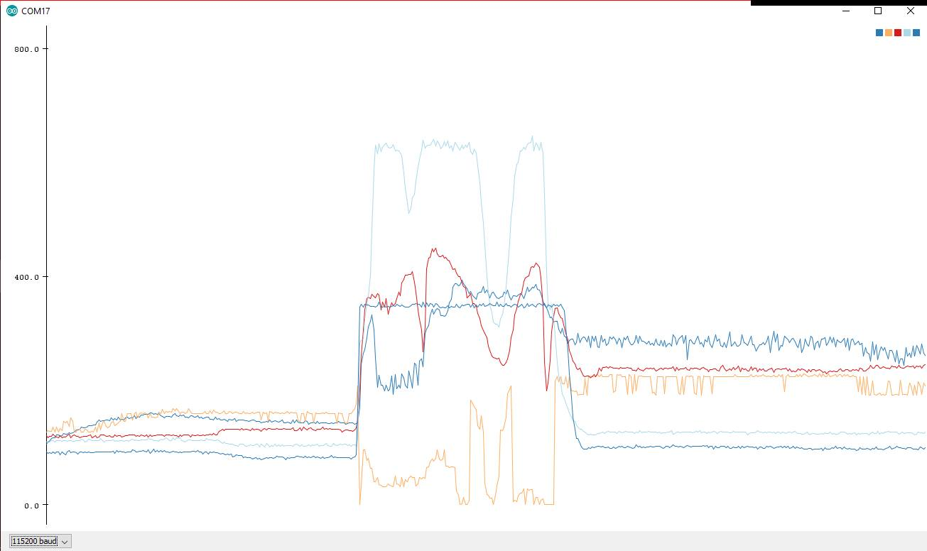
Arduino Serial Plot:

There is a link to ST’s documentation for the sensor (which includes that whitepaper) on the “Resources” tab of the sensor’s product page, but to make it easier to find, we added a direct link to the whitepaper there as well.

If you contact us via email about the sensor that is not responding, we will see what we can do to help you out. Please include pictures of the connections to the board as well as your sales order information.

-Nathan

1 Like

Thank you Nathan for your kindness

I ordered them from Botland (Poland), all working except the one, where I soldered an array of wires one hole further, which has destroyed it. So 11/12 should be operational.

And yesterdays problem is just a dust between XSHUT1…5 connector, all of them work today.

1 Like

What about interference problems with these sensors?

As soon as my robot start driving motors, no sensor work which has an XSHUT attached to controller.

The last one without it keeps working

That sounds like a complicated problem and it is not easy for me to troubleshoot with the limited information I have about your system, but I can recommend a few things to check. It is possible that the behavior you described could be caused by a brownout, which is a drooping of the supply voltage as large amounts of current are drawn briefly. You might consider adding some electrolytic capacitors across the sensor power rails to ensure they have a clean power supply. You might also check to be sure your signal wires are not in close proximity to the high current wires for the motors.

If your motors and the sensors are run from the same controller, you might try putting together a simplified test program to test whether a single motor and sensor (using the XSHUT pin) operate at the same time and gradually making the system more complicated again until it fails.

-Nathan

Dear Nathan

Thank you

There was brownout long before this question, as ION motion controller HV 2x60A 's BEC is only 200mA max draw…

But the XSHUTs with hardly any oscilloscope detection.I seen some pikes +/- 1V, so I assumed that induction from motor current is triggering the sensors to shutdown

I have solved the problem by pushing wires away from the motor wires.

Each XSHUT is connected by separate shielded wire with proper grounding at each point of destination

Found such wires inside an old VGA monitor cable from my junky box, which contains 4 strands shielded separately

So these sensors work better than industrial pepperl + fusch ML100-8-1000-RT/103/115

Like this

Thanks for letting us know what the problem was. Your robot looks pretty cool! Do you have more pictures, a video, or a link to a blog post about it?

-Nathan

Not at the moment as we fly tomorrow to Japan to compete in International Robot Sumo Tournament, I have your stickers for advertisement.

You may find older versions. After few month I will add the 3rd one.
Vytis 3
Vytis 2
Vytis 1

1 Like

Nice! Good luck in the tournament.

-Nathan

Uploaded Sumo Robot “Vytis 3” Making Pictures

1 Like

Dear andreidanescu,

When you used your addressing code I assume you used the Pololu breakouts. However, I am doing a small project and am waiting on my order to arrive. I am using the ST manufactured satellite boards and have no luck reading any data using even example code. Do you have a github with your addressing code and general pin to pin connection for the satellites? I am assuming once I get the pololu boards this process will simplify with the rest of the resources found inside this thread.

Hello,
I used the pololu code from these examples and all went well. Be careful of pullup values and wiring setup - the level shifters on these boards are quite “delicate” - not that they will break but they will stop working and take the bus down. We didn’t use the git but everything is standard on these boards - they don’t need any special layout. Hope this helps

There is a recently published Hackaday article that has a lot of good information about pullup resistor values, using I2C devices over longer wires, and in noisy environments:

Hackaday - Taking the Leap Off Board: An Introduction to I2C Over Long Wires

-Nathan

Hy i have 2 questions

1 : Xshout is tolerant to atmel atmega 328p gpio ?

2 : Cover window material can be made of glass or plastic !
i need some concrete types of this materials and ir filter materials (only plastic, no glass)

Thanks

Hello, gemforce.

As we state in the “Connections” section of the product page for the sensor, the XSHUT pin is not 5V tolerant, but there is a resistor on the board that will pull the pin to 2.8V, so you can toggle the state on a microcontroller like the ATmega328p that is running at a higher voltage by toggling the gpio pin between a high impedance state and actively driving the GPIO pin low.

We do not have any specific recommendations for using the sensor with a cover, but ST has an application note for using one that includes a specific manufacturer’s part.

-Nathan