Hello,
I know this sounds a bit silly maybe but I have ordered the TB9051FTG for RPI (mounted version) and later I saw there is also one available for te Arduino. Well looking to the datasheet of the TB9051FTG I think I still can use it when I connect all to the correct pins. I think I could even drive it with a Nano which uses 3.3V for digital I/O. I just can’t use the Python libs but will have to use a Arduino lib which makes sense.
Could anybody confirm this to me?
Thanks in advance
Ray
Hello, Ray.
Yes, you can connect your Arduino to the pins on the Dual TB9051FTG Motor Driver for Raspberry Pi (instead of a Raspberry Pi) and control it that way. It should be fine to use a 3.3V or 5V Arduino. If you make the same connections as the ones used on our Dual TB9051FTG Motor Driver Shield for Arduino, you should also be able to use our associated Arduino library.
Please note that the Raspberry Pi version does not pull up the EN and DIAG pins by default, so you would have to account for that by adding your own external pull-ups or controlling those pins from your Arduino.
Brandon
Thanks Brandon that clarifies a lot to me.
Could I ask you one more thing?
Im using the Pololu motors Item #4755 together with the board mentioned in previous post. Could you recommend a good batterypack for these? Im also using a Jetson Nano as the brain for the robot and as told I will use a Nano for talking between the Jetson and TB9051FTG.
I can always solder somesthing to create a good voltage for the Jetson and Nano. But the motors need a good battery pack so I wont need to charge up every 5 min.
I would appreciate to read your opinion/recommendation.
All the best
Ray
Hello.
LiPo batteries are a common choice for high-power applications like that. Unfortunately, I do not have any specific suggestions for one, but you should be able to find a good assortment available at RC hobby stores, or even online retailers like Amazon.
By the way, you can probably use the Jetson Nano to control the TB9051FTG driver directly, although we do not have any resources or example code for that.
Brandon
Hello Brandon,
I finally come at the point with my project to start using the hardware. But when reading the 37d motor datasheets I read that the encoders need a Vcc of 3.5 - 20Vdc but like we spoke about in a previous comment I would like to use a Arudino Nano which isues 3.3Vdc. So here I’m a bit confused because as the Nano uses 3.3 Vdc and the encoder need a minimum of 3.5 I would think this is not possible or do I mis something?
All the best
Ray
Good catch! While you could try powering the encoders at 3.3V, they might not work reliably. So, you could power them from the 5V pin on your Nano, then use either something like a logic level shifter or a voltage divider to drop the voltage of the encoder signals to an appropriate level before connecting them back to the Arduino Nano.
Brandon
thanks for the fast response!
Well I neede to think about that I could not find a 5Vdc pin on the Nano IoT but it must be there I guess cause it is supplied by USB.
Nevertheless I wanted to use it for the speed detection which have to be very accurate and fast and I think (just thinking out loud) using logic level shifters is more time delays. So maybe in that case it would be more interesting to use a MEGA.
Just to give you an idea of what I try to do:
I have a Jetson Nano running with ROS and I have the motor controller for speed control. But I thought it is efficient to use only one uC for the motors and another for sensors. Like that I can separate allsignals ROS separate which would be efficient.
Another option Im thinking of right now is just to create a separate power supply of e.g. 5Vdc with a 8705 but than I gues I would lower the voltages for the Nano aswel therefore you mentioned the logic level shifter I guess?
If you do not have a 5V source available, you could use your motor supply voltage, although a regulated source would be preferable. I generally wouldn’t expect a level shifter like the one that I linked to in my last post to introduce noticeable delays for a system like that (for reference it has quick enough rise times to allow for use with 400 kHz I2C signals). A simple voltage dividers would be even faster.
Brandon
Problem solved  just took a look at the pinout from the jetson nano which I use as well and it has a 5V output which should be more than enough the encoders use about 10mA so that will work perfectly
Oops problem not solved hehehe I will need some doesn’t like voltage higher as 3.3V and the encoder works only at 3.5 or higher. So I guess I need to buy a logic level shifter as you recommended.
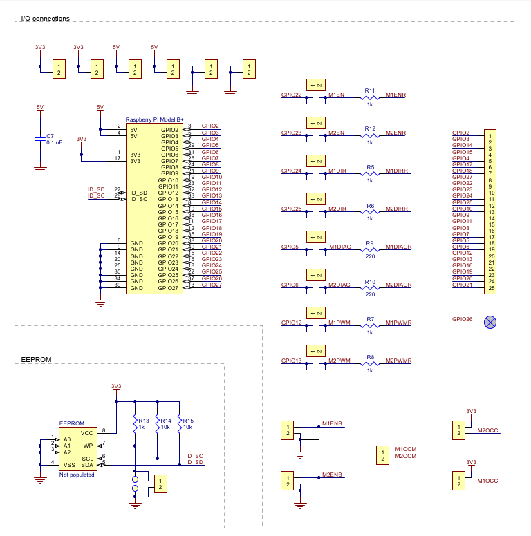
So if I understand the diagrams correctly I should connect the PWM output from the uC to pin 12 and 13 on the TB9051FTG? Hence that I cant plug the hole stuf on to a board I need to figure out the wiring for myself as stated in the first post.
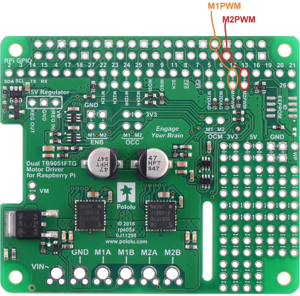
Each of the pins used by the motor drivers generally has multiple points that you can access it. They are labeled on the board and it should be fairly easy to follow the trace to see which other pins are connected to it. For example, here are the locations of the pins that you can use to send the M1PWM and M2PWM signals:
Please note that along with the PWM and DIR signals, you will also need to account for the M1EN and M2EN pins, since those are typically controlled by the Raspberry Pi (e.g. pulled low by default and driven high to enable the motor driver).
Brandon
Thanks Brandon!
Sorry for the late replpy I just came home yesterday evening. But the good news is that I was able to use the encoders with a logic level shifter as you recommended. I just finished the code and hooked up the wiring and all seems to work pretty nice. Although I noticed that the motors have some difference in speed even when I supply them with the same voltage source.
Tonight I will try to use the motor driver board and see if I can make this work. I will probably have to use some PID control to get them running exactly the same. Else my robot won’t drive straight
I forget something to mention
The black header, do you know from experience if it is easy to desolder this? I have a desoldering heat gun but I’m affraid to use it cause I don’t know what temperature would be good to set it, I don’t want to burn the comopnents on the pcb.
The way I usually remove such headers is to sacrifice them as I have more anyway. Just use sharp side cutters to cut the plastic of the header between every pair of pins. I will admit that this is harder to do with double width headers like that though. Usually you can then remove most of the plastic and just have the pins left. You can then desolder the pins one at a time using a normal iron at normal soldering temperatures.
Clear yeah maybe I have to try it that way or leave it as it is. I tried it with a blower but that didn’t work out well
Hi Brandon,
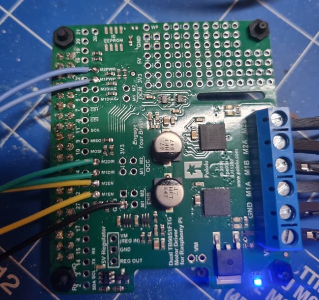
I’m trying to make the board working bu tI think I do something wrong. I don’t measure any output so the motors won’t run.
What I did is set to enable pin HIGH, set the Direction pin High and supply a PWM signal to the driver board. At the output of the Arduino Nano I measure the correct PWM signal and also the pins that I set HIGH are measured such.
I applied 12Vdc to the board and see the blue led on. But no output appears I must doing something worng but I don’t know what I am doing wrong?
Here’s a picture of what I have connected and where.
Please note that the PWM input so PWM output from the NANO IoT to the Motor Driver Board is 3.3V I’m starting to have doubts that this is the issue
It is normal for brushed DC motors to have some unit-to-unit variation in speed like you described. If you want to ensure your robot drives straight, using the encoders to match the speeds is a good solution.
Depending on your tools and experience, that header could be quite challenging to remove. AdamGreen’s suggestion of sacrificing it to make it easier to remove one pin at a time is probably the easiest route, but still wouldn’t be trivial. For the temperature, as AdamGreen also mentioned, standard soldering temperatures (e.g. something between 350°C and 400°C) should be fine.
That board typically gets its 3.3V and 5V logic voltages from the Raspberry Pi, so you will need to supply those as well (to any of the 3.3V and 5V pins, respectively).
By the way, if you are powering the Arduino Nano IoT from USB, this Arduino documentation explains how to enable the 5V output pin by shorting the appropriate pads on the underside of the board.
Brandon
Yes I placed that jumper to be able to use the 5Vdc.
I measure on the output of the Nano a PWM signal which is the input to the driver board. There I supplied a 12V power supply but on the outputs I measure nothing 0 Vdc. I must do something wrong but I can figure out what.
So do I need to give the Motor Driver board an extra power supply? The PWM signal is based on a 3.3Vdc voltage.