Here is a picture with what I measure
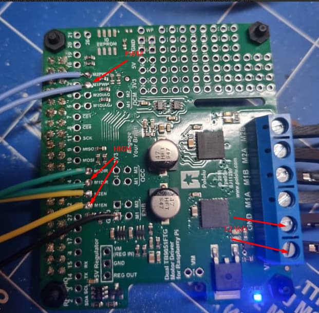
Note that the logic values are based on 3.3V. So the enable and dir are 3.3V high and the PWM amplitude is also 3.3 V
Here is a picture with what I measure
Note that the logic values are based on 3.3V. So the enable and dir are 3.3V high and the PWM amplitude is also 3.3 V
As I mentioned in my previous post, you will need to connect 3.3V and 5V supplies to the driver board for logic power. You can do this through any of the 3.3V and 5V pins, respectively.
Brandon
I understand you but I dont know how to connect it … sorry
It is not clear to me where I should aply a 3.3 and 5 V supply
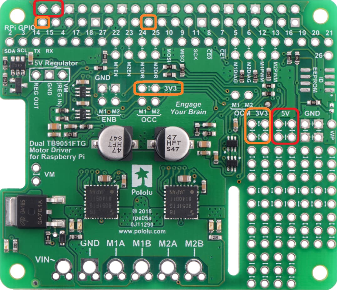
I have indicated the pins you can connect the 3.3V power to in orange and the pins you can connect the 5V power to in red:
Brandon
Just did that but still it doesnt work
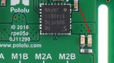
doing so this red light get on
Could you explain in more detail what you mean by “it doesn’t work”? For example, what are you expecting to happen compared to what is actually happening?
To clarify, that red LED is the M2 motor indicator LED, so if that is lit up, there is a voltage differential on the output. The green LED next to it will light up when the polarity of the output has flipped, and the brightness of the LEDs changes with the duty cycle.
Brandon
Im sorry I was not clear enough at the time of writing my last post one motor did work but the second one did not run. I checked a bit with my scope and discovered that I made a mistake with the wiring cause the motor driver board did not receive a PWM signal from the Arduino. All solved now. I was even able to use a PID control and tune it.
One thing I noticed though on the motors that theye have pretty high back EMF’s whcih my power supply doesnt like a lot I think this will be solved when using batteries.
But I like to say you have helpend me tremendously!!!
Small fun update:
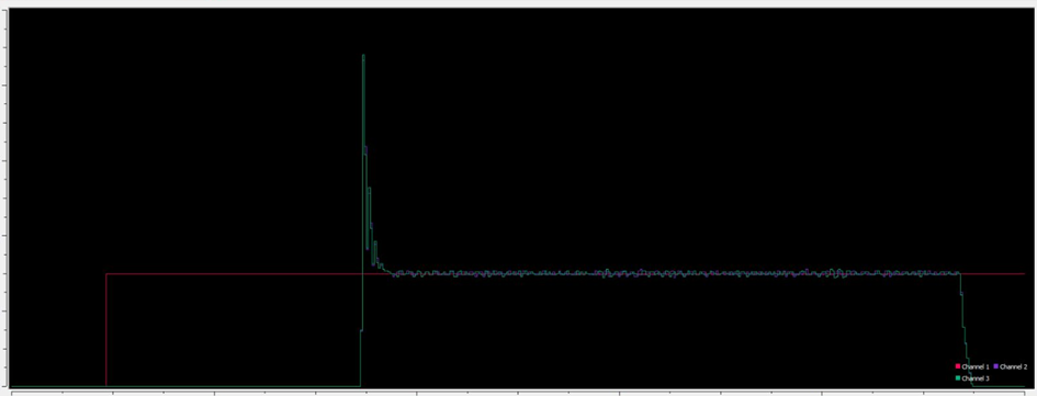
This is the result from 2 motors running with the Motoro Driver and using a PID control in a Nano 33 IoT. I gave a setpoint of 5000 rpm (motor speed). Both motor running almost equal its a pitty there quite some overshoot. But this is tested on the workbench so there is no damping and I therefore dit not use Kd yet.
I first want to adjust my code such that it takes care of the gearratio of 102.08 (in other words I use the outgoing shaft as setpoint) and place the battery (which made a huge difference, don’t use a regular power supply with the kind of controls). Cause weight will cause already natural damping but maybe later I will have to introduce a Kd value to have less overshoot but so far this is pretty cool.
I thought it would be nice to give a small update.