I am using the following motor pololu.com/catalog/product/1200
I am using it as a bipolar stepper and the A4983 driver, calibrated at 70% rated current.
I find that at less than 15rpm, the motor starts fine and gives me the desired rpm.(Verified with an encoder)
But when i start at 50 rpm, with the same load as before, i notice that the motor shaft doesn’t even rotate. If i give it a substantial push, it sometimes picks up speed to 50rpm.
When repeated at 100rpm, it doesn’t continuously rotate even for a substantial push.
What could be wrong.
My load doesn’t seem, to be that high, as i can easily move it even with my finger.
Can you explain how you have the A4983 wired, and what kind of power supply you are using? How did you set the current limit? Are you using microstepping? How many times are you stepping per minute to achieve 50 RPM?
The behavior you are describing is not necessarily indicative of a problem. To get full speed out of a stepper motor, you typically need to accelerate it to that speed. You might be able to improve performance by using a higher voltage or increasing your current limit, though setting a current limit higher than the stepper motor’s current rating can damage the motor.
To understand why this is the case, you can consider how a stepper motor works. Every time you command a step, you are rotating a magnetic field slightly and then, ideally, waiting for the rotor to re-align with the new field. If you step the magnetic field again before the rotor has aligned sufficiently with the field previous step, the stepping sequence is disrupted and the rotor will likely be pulled by the new field back in the direction from which it came, keeping it from ever building up speed. When the rotor is at rest, it takes longer to re-align than if it is already spinning at some intermediate speed.
That said, I expect you should be able to get more than 100 RPM with this motor (with no load), so there might be a problem with your power supply or current settings, or you might be underestimating the impact of your load. The answer’s to the questions Ryan asked above can help us figure out if you are doing something wrong.
I calibrated the motor according to this guide A4983 and A4988 Getting Started Guide.
I am using 1/2 steps to achieve 50 rpm.
Things seem to work fine till 15 rpm. I increase the rpm by decreasing the time delay between the low to high transitions. I checked it with a stopwatch and an encoder. Will also post the code.
My voltage input going into the vmot pin during calibration and during runs is 12V DC
Given that the stepper motor you are using is rated for 1.2 A per phase, it seems like you might be limiting the current too much. If you put your driver in full-step mode and hold the step pin steadily high or low, how much current does your stepper motor draw? I expect it to be around 1.7 A. Also, what voltage do you measure on the ref pin?
Once you’ve verified that you have set the current limit to the correct value, I suggest you also try raising the motor voltage significantly and see if that has an effect.
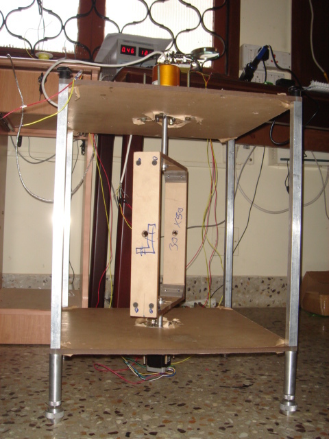
Can you post a picture of your system so we can see what your load looks like?
I have put the driver in full step mode(previously i was making it do half steps)
The code is as follows
#define stepPin 8
#define dirPin 9
#define enablePin 7
#define delayl 15 //corresponds to 20 rpm at full steps

void setup()
{
  pinMode(enablePin,OUTPUT);
  pinMode(stepPin,OUTPUT);
  pinMode(dirPin,OUTPUT);

  digitalWrite(enablePin,LOW);
  digitalWrite(dirPin, HIGH);

  Serial.begin(115200);
  Serial.println("Type any character to start");
  while (!Serial.available());
}


void loop()
{

    digitalWrite(stepPin,LOW);
    delay(delayl);
    digitalWrite(stepPin,HIGH);
    delayMicroseconds(2);

}
I have attached a picture of the setup. The motor is below, encoder is on top. The aluminium shaft that goes through the frame is held by bearings. The rectangular thing in the middle is made of acrylic and is very light.
So coming to the tests,
If i maintain the step-pin at high or low all the time, my power supply reads 0.46Amps at 12 Volts.
Which is the ref pin? I am using the driver without the on-board regulated power supply?VDD is connected to an Arduino digital pin.
At 20 rpm, the motor does not spin. If i give it a nudge it starts spinning. If i increase voltage to 24Volts, the spinning appears to be less jerky…
This lets me acheive 60rpm in the loop() portion of the code.
I tried to ramp up to 100rpm, but the whole thing stops rotating at some point of the rampup, so i switched it off.
I located the vref pin.
When i maintain the step pin at low and the driver continues to be in full-step mode, i measure a voltage of 0.368 on vref.
according to the datasheet, Itrip = vref/(8*.05)
Since i want Itrip to be 1Amp, shall i turn the pot till vref =2.5?
A vref of 0.368 V results in an ITripMAX of 0.92 A, which is pretty close to your 1 A goal. I was making the mistake of relying on the output current of your power supply to judge the coil current of your stepper motor, but this is not a valid approach. Because of the inductance of the stepper motor coils, current can be flowing through the coils even when the power supply is not supplying it. If you want to be sure, you can use a multimeter to measure the current flowing through one of your stepper motor’s coils. If your current limit is set properly to 1 A, you should see approximately 700 mA if you are in full-step mode with the step input held at a fixed voltage (either high or low).
I think your issue really comes down to the fact that your load is much more substantial than you think it is. To see if this is the case, can you see how the stepper motor performs with the load disconnected (you can use a small piece of tape to help you track the output shaft as it rotates)? If you want to achieve higher speeds with a load like that, you will need to build acceleration into your stepping routine.
Also, if you want to maximize your stepper motor performance, you should use your power supply near its maximum voltage. If you do this, however, please note that your long power leads could result in dangerous LC voltage spikes that could push the motor voltage past its 35 V limit. One way to protect your driver from these would be to put a large electrolytic capacitor across power and ground near your stepper motor driver.