after reassigning the input pin to digital 3 interrupt 1 it still gives me the same error. I switched to an uno and a new driver board as the original driver board failed first time testing a previous version of the code.
on this new setup I have ran the demo code and it works fine driving the motors forward and reverse as it should, I have not tried this updated code with the driver board yet as it fried it last time (previous code) but trying it with just the uno and rc receiver it gives me the m1 fault code still. do i have to have the driver board hooked up to test the code?
Sorry we missed seeing your post and for the delayed response.
It looks like you forgot to call md.init() in your setup() function in your code, which enables the internal pull-up resistors for the two fault lines (!M1FLT and !M2FLT) as well as configures the correct pin modes for the rest of the motor driver’s pins. Can you add that line to your code and try running it again without the driver connected? Please let us know the outcome.
ok the good news is that fixed the issue. bad news is it ran for a second and stopped. this fried the uno and caused the driver board to put out m1 fault again (after installing a new uno). I think I found the issue though, these motors are reading .37 ohms this comes out to over 60 amps at 24v.
new question is will this driver board run these if current limiting (is that a thing)is applied?
It sounds like you might not know that the dual G2 HPMD shield has an active current limiting feature. (You can find more information about current limiting from this Wikipedia page.) By default, the active current limiting threshold for the dual G2 HPMD 24v14 shield is approximately 40 A and can be adjusted lower by connecting an additional resistor between the VREF pin and the adjacent GND pin. (You can find that information in the motor driver’s user’s guide under the “Control and feedback pins” section.) The current limiting feature is practical for cases where the motor might draw only a few amps while running but can draw many times that amount when starting, however, your motors sound like they’re much higher-power than what we would recommend our G2 HPMD (and controllers) be used for. I suggest looking at the RoboClaw Motor Controllers, specifically the RoboClaw 2x60A Motor Controller (V6) version, which is probably better suited to run your motors.
I’m revisiting this again. Here is what I have but it will not compile for some reason I can not grasp. I’ve been pulling the remainder of my hair out for a week trying to get this to work.
is there already an pololu example that takes an rc controller to use with the motor driver products?.. if not, could some one there write one so I can move on with my life.
The reason your ROBOT_CODE_REVISION_4_2.ino cannot compile is because you have a lot of code that needs to be inside a function, but it’s not. For example, at line 61, after the end of the ppm_write function, you start a block of code that calls the ppm_interrupt() function. Similarly, at line 68, after the end of the ppm_interrupt() function, you have a lot of code that probably should be inside a function.
ok I fixed those issues and got it to compile but it still gives me a m1 fault code no matter if its arduino with or without the md or with or without the motors connected.
testing it with only the arduino omitting the stop if fault lines it prints out the rc receiver mapped inputs perfect.
Can you provide a link to the datasheet (or product page) for the motors you are currently using? Can you post your latest code, including the recent changes?
By the way, I missed addressing the question in your previous post. We do not have any RC examples or code for our motor drivers and cannot help you write the code specifically for your setup. I suggest adding some print statements to make sure that your motors’ speed values are being processed as expected.
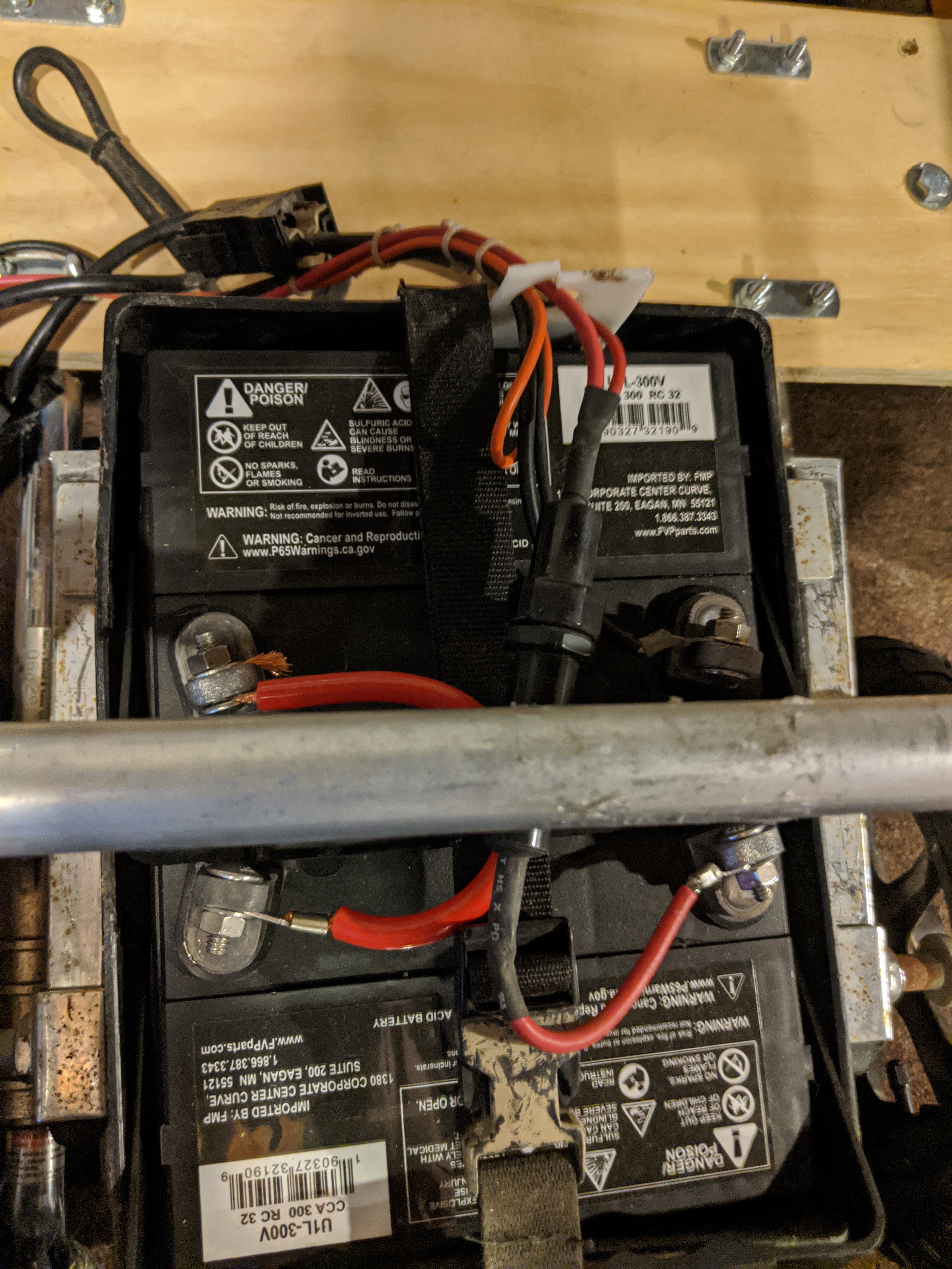
the motors are fengguang power chair motors from the early 2000s. I googled the numbers on the tag but it came up slim results not associated… I will add the print statements and see what is happening on that end. As the motors function fine with the demo, I assume it is my code.
In my opinion pololu putting out an example sketch using an rc controller to operate its boards would be advantageous to the sales of their products. Having some thing that is virtually plug and play is a great incentive to new makers (myself included). btw this ppm decrypter is for the very popular flysky rc receivers.
Although we do not have any RC code for our motor drivers, we do have motor controllers with an RC interface. If you’re looking for an RC plug-and-play solution in a motor controller, you might consider getting one of our Simple Motor Controller (SMC) G2 motor controllers. (You would need to get a pair of them since they only have one motor channel.) They have similar power characteristics to our G2 High-Power Motor Drivers, so if your motors work fine with the driver you have, they would probably also be fine with the corresponding SMC.
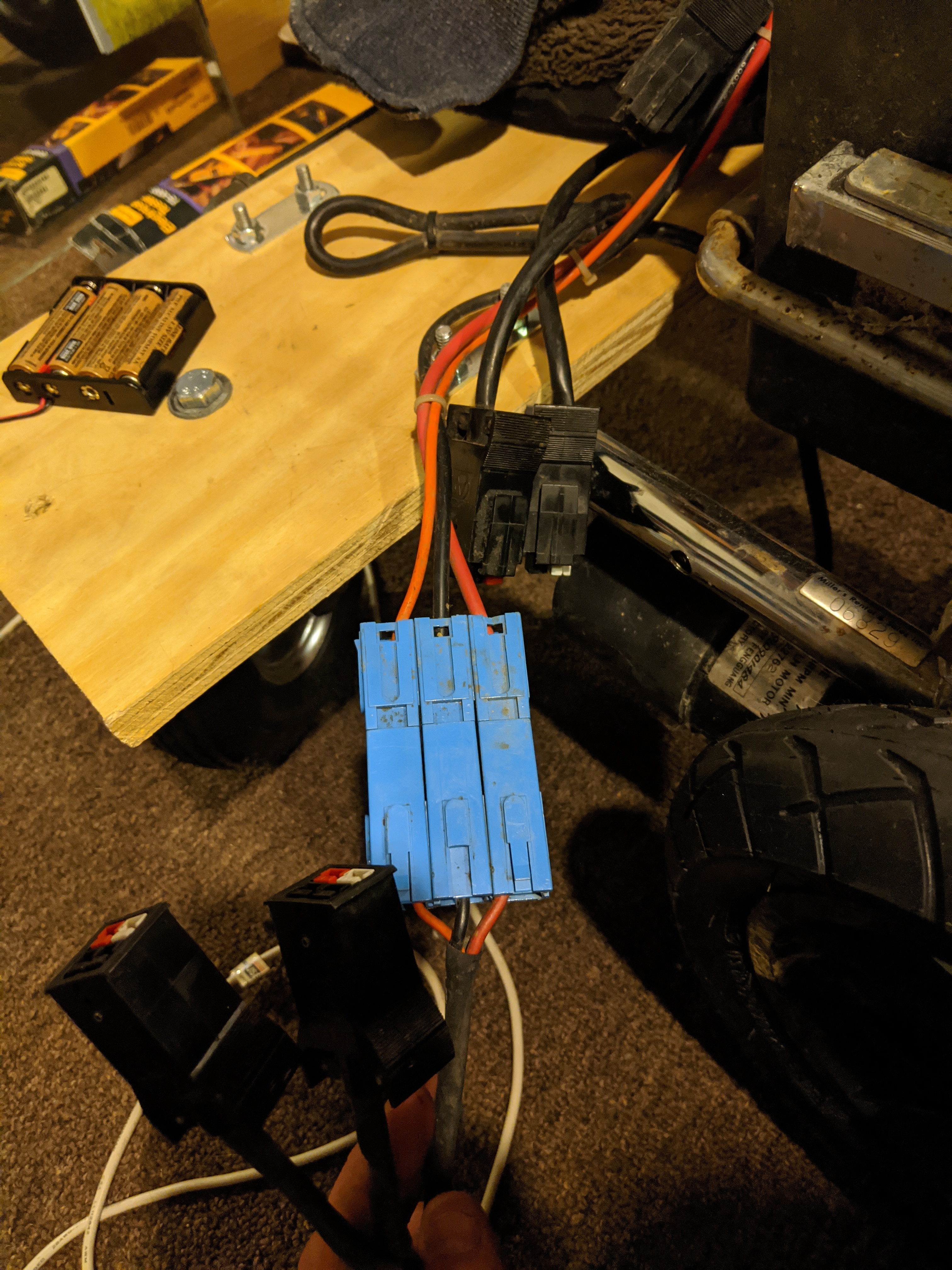
Considering the demo sketch works but your code doesn’t for the same setup, it does seem like there’s something wrong with your code. Again, if you can post pictures clearly showing your connections and setup and your latest code, we can better help you narrow down the source of the problem.
I have added the print lines. When I comment out the md lines it shows the correct motor speeds.
I tried the demo sketch again and it shows m1 fault as well.
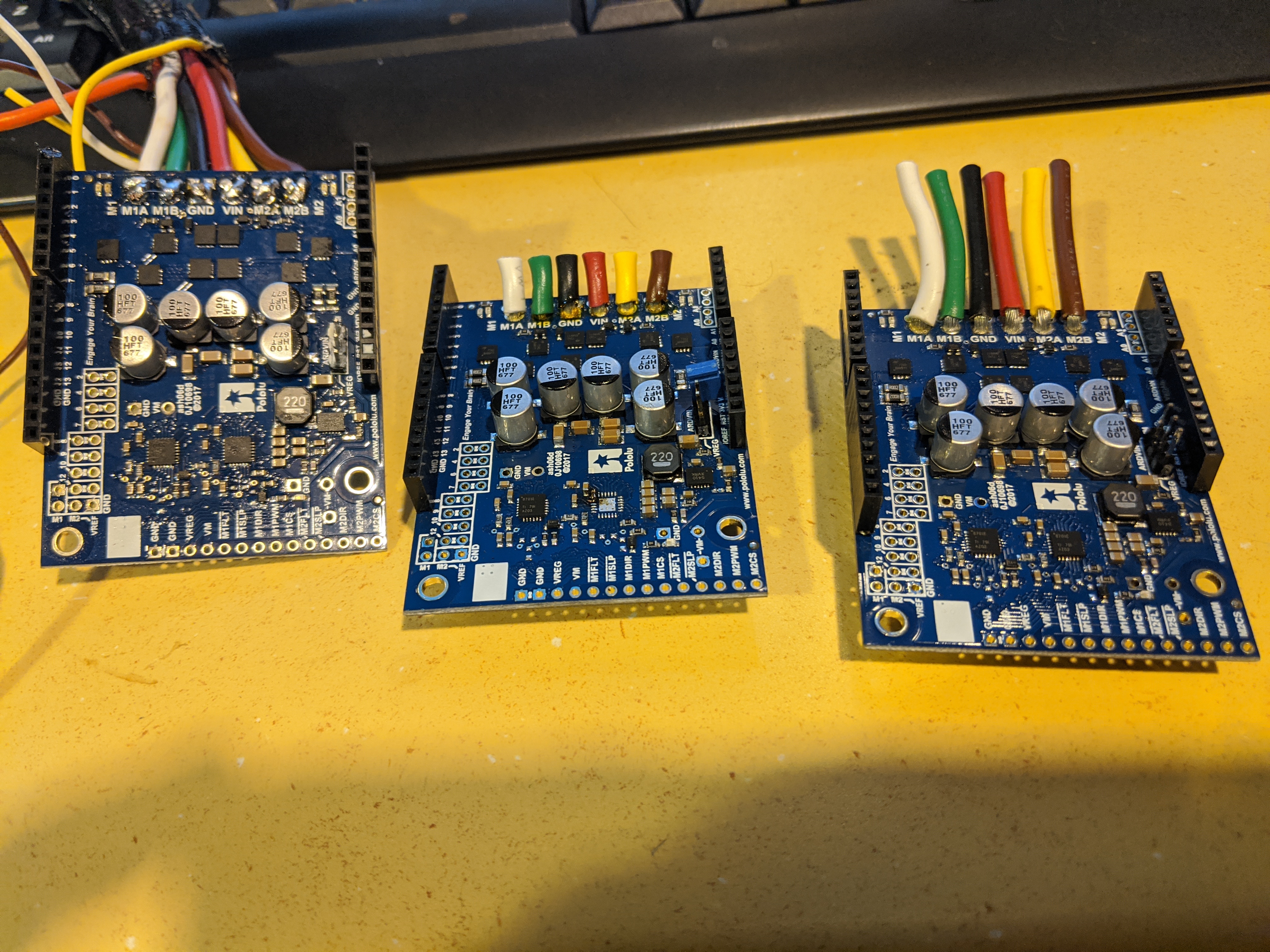
this is the 3rd one of these very expensive motor driver boards I have gone through with no run time before this m1 fault error showed up. the boards have no visible damage to them what gives?
the board in the middle I shorted and blew it up but the other 2 are visibly undamaged but bring back the error even in the demo.
We test every unit we make, so your units were probably working at some point, and given this is now the third unit you are having trouble with, I think we should look more carefully at your setup.
Firstly, I do not see md.init(); (or md.calibrateCurrentOffsets();) at all in your attached code. (You mentioned adding them here. Could you have uploaded the wrong code?) You need to call the DualG2HighPowerMotorShield library’s init() function before using the shield. As I said in my earlier post, that function configures the correct pin modes, including the two fault pins, on the shield. The two fault pins are open-drain outputs, driving low when a fault is occurring, so to use the outputs, they must be pulled up to your system’s logic voltage. You can find that description in the table under the “control and feedback pins” section of the Dual G2 High-Power Motor Driver Shields for Arduino User’s Guide.
Secondly, from your pictures, it looks like there might be a stray wire shorting the two channels for M1 on the current shield you’re using, which could explain why the !M1FLT pin is triggering. Can you post close-up pictures showing all the soldering joints (top and bottom) on your current shield?
Considering you are also getting the fault when running the demo sketch, it seems like there is another issue. If you have another Arduino board, can you try that in your current setup (after double-checking that none of your pins are shorting together) and let us know the results? (You can do a continuity test using a multimeter to verify that none of the pins are shorting/connecting to any nearby pins.)
do I need to physically pull up those fault pins or is it done in the library files?
I believe that “stray wire” is a piece of hair that fell out from the stress this thing is causing me.
I have it running through a mega this time but still m1 fault.
m1a 5kohm to ground any other pin is 3Mohm
m1b,m2a and b all have around 3Mohm to ground and or each other
measuring the 2nd board I bought all pins are 3Mohm to each other or ground
supply voltage to supply ground is about 1.3 Mohm onall boards
I can’t see any conection on that pin to ground so I believe it may be shorted internally?
I am going to try wiring in the second board one more time and see how it goes.
Calling the library’s init() function enables the Arduino’s internal pull-ups on pins connected to the !M1FLT and !M2FLT pins on the shield, so you do not need to add external pull-ups. However, it shouldn’t hurt to add external pull-ups to the fault pins, so you might try doing that and see if it make any difference. (You can see how the library enables the Arduino’s internal pull-ups in the init() function here.)
I measured the resistance across the motor outputs and VIN to GND on a dual G2 HPMD here and got values similar to the measurements you got from your second unit. For your first unit, you said you measured 5 kohm between M1A and GND. That value does suggest something is wrong with the board.
With your second unit, can you try measuring the voltage on the fault pin(s) when a fault is reported to eliminate any possibility that the Arduino pin is not reading it properly (both with and without the external pull-up)?
well as expected it still shows m1 fault in the serial monitor.
I have tried with and without the additional pull up resistor installed and same thing.
I would have to say the units I bought must have been faulty, can I return them for testing?
Unfortunately, having you sending your units back for us to look at is something we cannot offer right now while our operations are being so severely affected by the coronavirus pandemic. If you want to continue troubleshooting, we are still happy to help.
Out of your three units, it sounds like the second unit has the fewest indications of being damaged, so can you disconnect everything in your setup and only plug the USB cable and shield into the Arduino Uno and connect power to the shield? Then run the unmodified demo program. Do you get a fault?
If no error occurs, with the same setup, connect the motors to the shield. Does that cause a fault?
If you get a fault, can you please measure the fault pin (M1FLT or M2FLT) corresponding to the fault being reported? It should be either pin 6 or 12 on the Arduino if you have not remapped them. What voltage do they show?