Unfortunately, having you sending your units back for us to look at is something we cannot offer right now while our operations are being so severely affected by the coronavirus pandemic. If you want to continue troubleshooting, we are still happy to help.
Out of your three units, it sounds like the second unit has the fewest indications of being damaged, so can you disconnect everything in your setup and only plug the USB cable and shield into the Arduino Uno and connect power to the shield? Then run the unmodified demo program. Do you get a fault?
If no error occurs, with the same setup, connect the motors to the shield. Does that cause a fault?
If you get a fault, can you please measure the fault pin (M1FLT or M2FLT) corresponding to the fault being reported? It should be either pin 6 or 12 on the Arduino if you have not remapped them. What voltage do they show?
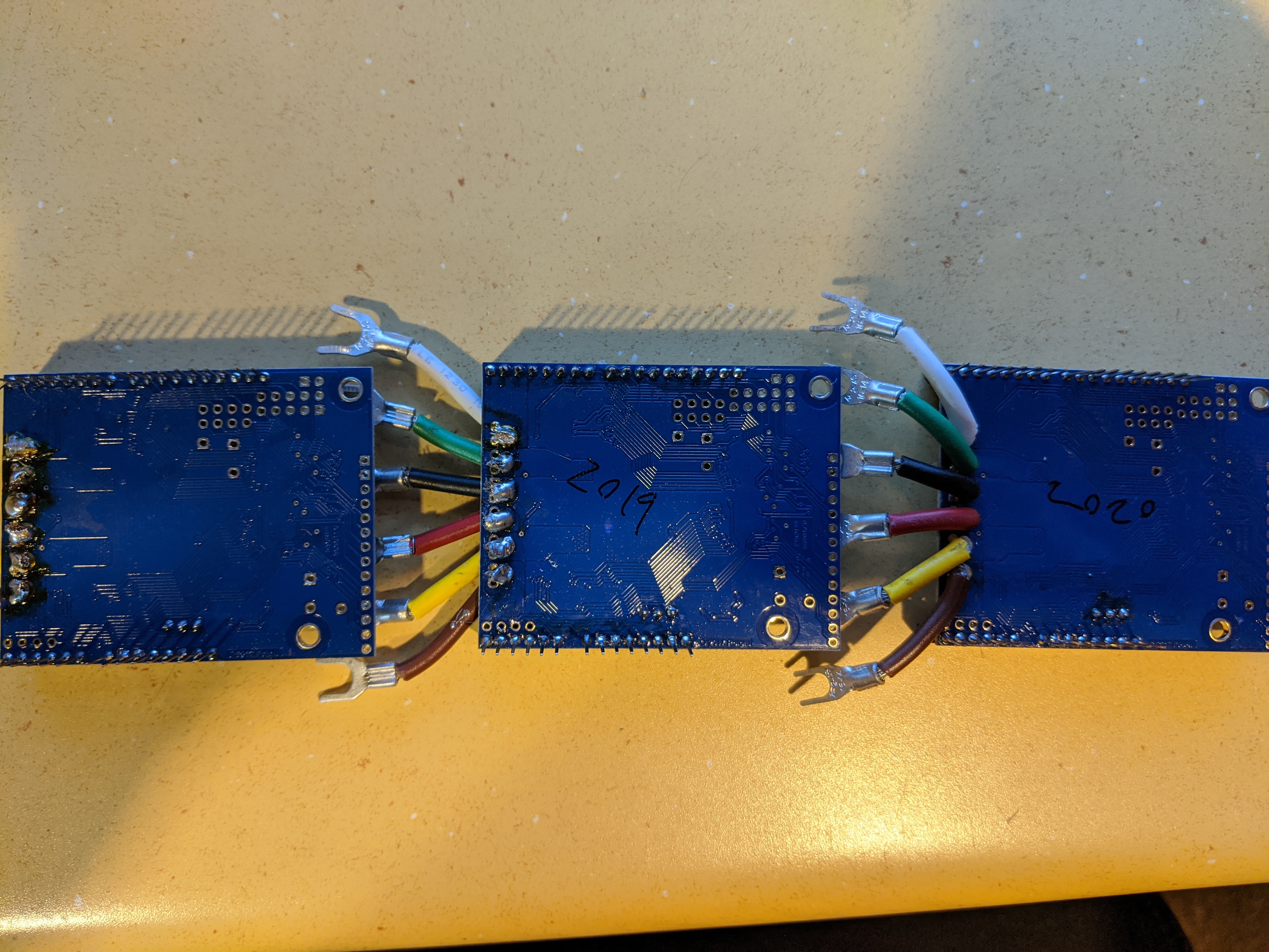
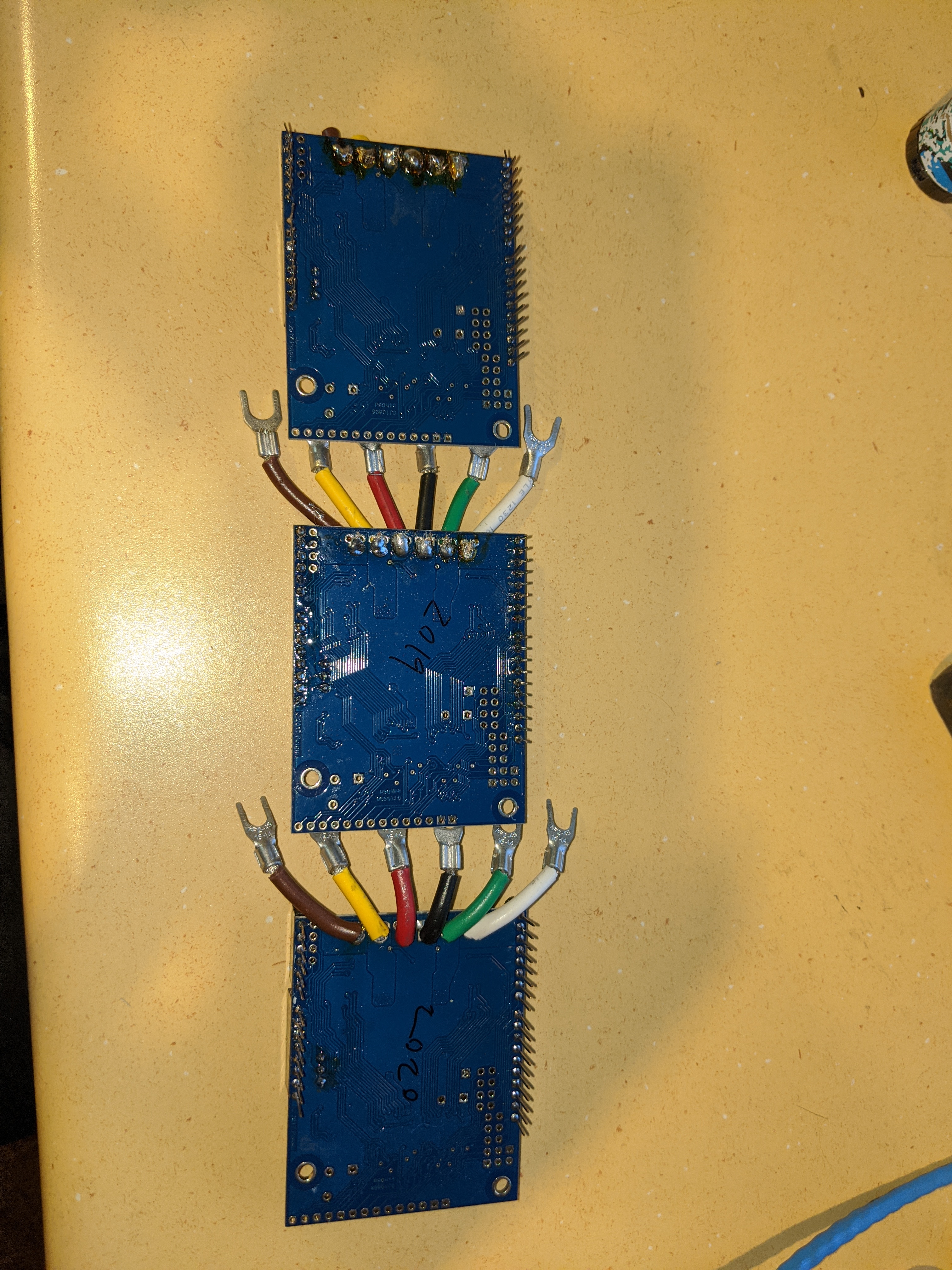
Can you post pictures showing the underside of all three of your boards, including the unit you tested with? Also, can you email us with your salesorder information and reference this thread?
I emailed support with all the information needed.
the unit I recently tested was the one marked 2019 …respective to how long I have been screwing with this
I replied to your email, but for the benefit of other readers, some of the soldering joints for the motor and motor power connections do not look good. Since they could contribute to intermittent connections or shorts that risk damaging the driver, I strongly recommend trying to improve them (at least on any further units you try). It can be hard to get those joints soldered cleanly because there is so much copper in the board drawing heat away, so if you do not already have a good quality soldering iron, it might be worth looking into getting one.
I assure you my solder joints are good and strong and have nothing to do with this problem. Although they look chunky they are making excellent contact with both sides of the driver board with no pin shorting. how do you expect 10 gauge wire to look soldered by hand to a pcb.
Although I had some code issues initially with the sleep pin, that part of the code was not used on the latter 2 boards. the code works fine with other drivers. I believe these boards can not take the rapid forward reverse switching of a joystick.without some sort of delay.
I’m further irritated that the company keeps deferring me to buy more hardware when there is a problem instead of figuring out what happened.
I’ve already spent $150 on these boards and have not been able to use them.
my motors are tested to consume 2.8 amps free spinning and about 9 amps stalled.These boards should be more than capable of delivering what I need.
I’m not purchasing more boards nor would I recommend pololu’s products until this gets rectified
As I mentioned, we test every unit, and they were all initially working for you as well, so it seems clear something is happening in your system to damage them. I suspect something about your system is more demanding that you think it is, and it is possible these boards are just not appropriate for those conditions. You mentioned your motors draw 2.8 A with no load, which would make it unlikely that the stall current is just 9 A, since the stall current is usually more like 10-20 times the no-load current. Stall currents are notoriously difficult to measure accurately, especially when they are high, so special measurement techniques are often required. How are you measuring the stall current? Also, how long are the leads between your power supply and the driver?
These are especially important questions if your motors are rapidly changing direction. Can you elaborate on why you think rapid switching of direction is the problem?
Also, you mentioned that your code works fine with other drivers, which makes it sound like you have a different solution that already works. Is that the case? If so, can you let me know what these other drivers are and why you don’t want to just use them for this project?
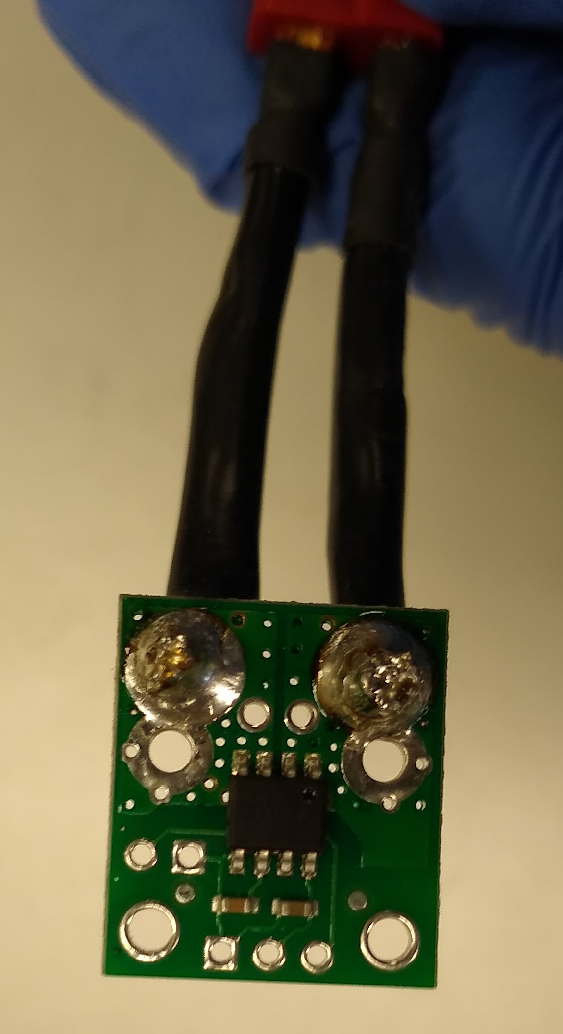
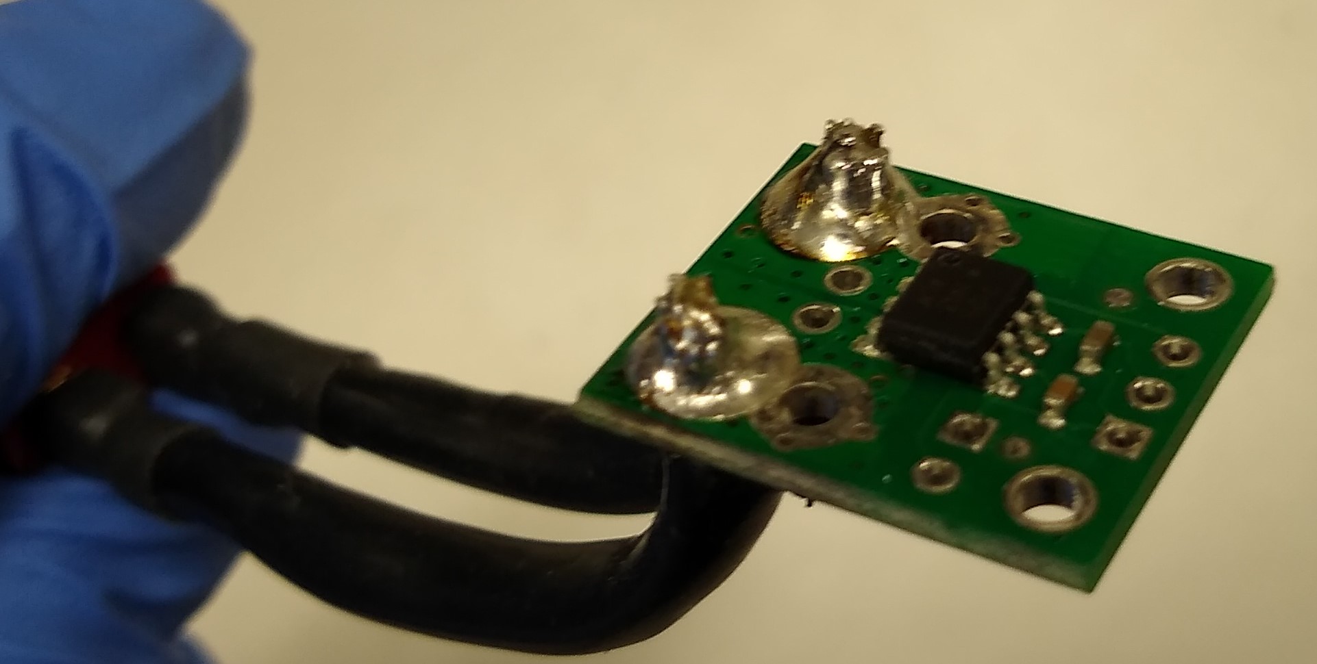
With your soldering, it’s not a question of the joints being strong enough, it’s just that they are objectively flawed in an electrical sense. You can compare them to this list of common soldering problems for a more detailed explanation. They might be making okay connections, or they might not; the problem is it’s impossible to tell from inspection. At the point where you are having unexplained problems, that is not the time to be dismissive of glaring potential causes like this. The following pictures show what good solder joints for thick wires should look like:
I know they are tested before leaving your hands. It is totally possible that something in the setup could be wonky “stall” current was measured by adding as much resistance as I could apply holding the drive wheel with a rag. that being said I understand actual stall current is much higher. I don’t believe having the drive wheels unloaded would apply this current.
the driver setup I am testing with now is a group of 8 relays (4 for isolation)and a servo turning a pot on a basic pwm motor driver…It’s super crude and offers very choppy steering response
Here is my issue with these boards, I have had this setup running with a 2 axis joystick when I first started the project as well as the demo code. I had some serious issues with the code before and haven’t had it running on the driver board since. I Can’t understand how a motor controller can stop functioning from the 1/2 a second of unloaded jitters that I got out of it…
Now that I know this seller calls for a 60 amp motor controller for these I would not have purchased the 24v14 although it ran fine with an analog joystick. I even sat on it while driving it around no problem
A motor will draw its full stall current upon abrupt application of power, and it can draw up to twice its stall current when switching directions abruptly from full speed in one direction to full speed in the other, so if your code was inadvertently changing the motor speeds many times a second, that could easily have subjected the drivers to much more stress than if the speed is varied more gradually.
I’m sorry you had a frustrating experience with your G2 HPMD 24v14 boards. As Amanda mentioned, and given the 60 A controller recommendations you linked to, it’s very likely this driver board is just not generally suitable for the power draw of your motors (even if it seemed to work for a little bit). In addition to the recommend controllers, you might also consider the Roboclaw 2x60A, which I expect to be comparable. Like the others, it can accept RC pulse inputs, which should help you get started without requiring any microcontroller coding.