
Can the control voltage (setpoint) be configured to use the entire 0-5 analog volt range to control motor speed in one direction only? The user guide seems to say the first half of the range is used to control speed in the reverse direction. Does it have to be that way? I have an application in which I do NOT want the motor to run in reverse.
Hello.
You should be able configure the jrk to only go in a single direction by checking the “Asymmetric” box under the Scaling section and setting the “Input” and “Target” values appropriately. The picture below shows what the values for the Scaling section should be if you are not using feedback.
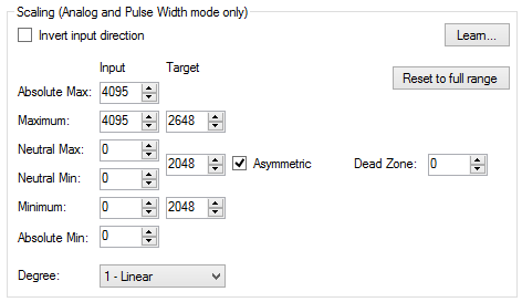
Please note, the “Target” values will change depending on what feedback mode you are using.
- Jeremy
Thanks Jeremy. Fedex will be delivering my controller today.
For feedback I’ll be using a 250 cpr encoder on a 0-6000 rpm motor. If you would please complete your configuration example I would be most grateful.
I just received my 21v3. I’m now waiting for Fedex to deliver the encoder so I can install it on my motor.
I’m looking at the 21v3 configuration screens but I don’t understand how to configure encoder feedback. The “Feedback” configuration tab shows the feedback range of values is 0 to 4095. How do relate that range to the physical rpm range of the motor (0-6000)? That is, where do I specify how many feedback pulses (counts) from the encoder represent one rpm (250 cpr, counts per revolution)? Or that the pulse rate at maximum rpm is 25k pulses per second (6000 rpm X 250 cpr = 1.5e3 pulses per minute = 25k pulses per second)?
I apologize if this stuff is obvious to most people but not to me. I’m trying to “Engage My Brain” but I guess I’m a little slower than the typical Pololu customer.
thanks!
Hello.
Your questions sound similar to a phone call I had earlier this week. Did you call us with questions about the jrk?
You can find information about how the feedback works in the “Feedback Options” section of the jrk user’s guide. Please note that using an encoder as tachometer feedback would fall under the “Frequency (digital)” feedback mode.
When the jrk is in this feedback mode, the feedback value is 2048 plus or minus the number of ticks received from the encoder signal (depending on the direction the motor is being driven). There is no built-in configuration parameter to specify how many counts of the encoder corresponds to one RPM. Instead, the jrk will adjust the speed of the motor so that the number of counts from the encoder matches the set target value (minus the 2048 neutral point). For example, if your PID period is 1ms (default), and you set your target to 2073, the jrk would try to spin the motor forward at a speed that would result in 25 counts of the encoder every 1ms. Using the number of counts per revolution your encoder gives, you would be able to calculate the motor speed that this corresponds to.
Please note that when the jrk is set to “Frequency (digital)” feedback mode, the scaling values Jeremy recommended would probably not work correctly. I recommend adjusting your feedback scaling so that at the maximum speed of your motor corresponds to a feedback close to 4095. You might also try adjusting your PID values if your system is not reacting how you expect.
If there is something specific you do not understand, please let me know and I will try to clarify it for you
-Brandon
Brandon,
Yes I called last week but I still wasn’t able to make sense of jrk configuration. I posted my question on the forum to see if any users might have actually configured a jrk to do what I’m try to do. My goal (below) seems pretty common and straight forward but I’m not able to complete the configuration from the information given in the User Guide. The User Guide is oriented toward position control, not frequency control. A configuration example or two would be extremely helpful.
On page 17 of the User Guide, Feedback configuration is discussed. The Feedback configuration screen contains adjustable “Calibration” values. I can’t figure out what values to put there. My application consists of a motor that I want to control the rpm (speed) in ONE direction. The rpm will go from 0 to 5000. The encoder cpr (counts per revolution) is 250. At maximum rpm (5000) the encoder pulse frequency will be 20,833 pulses/sec (5000rpm X 250 cpr X 1/60 minutes/sec). How does this frequency range (0 to 20,833 pulses/sec) relate to the “Maximum” and “Minimum” values shown in the “Calibration” column? How do I make 4095 represent 20,833? What is 4095? Is it the number of pulses per PID period at maximum speed? Also how does the information on the Feedback tab relate to the diagram on page 7? Where does feedback “scaling” take place? Does the software scale the “Calibration” values (0-4095) to “Scaled feedback” ranges of 0-2047 and 2049-4095 as required at the summing junction where the error (Target - Scaled feedback) is calculated?
Page 15 of the User Guide discusses “Input” configuration. From that discussion, and others in the User Guide, it appears that a Target value of 2048 produces zero duty cycle PWM output. But what happens if you check the “Asymetric” box move the neutral value to 0 instead of 2048? How does this impact the scaled feedback configuration? Doesn’t scaled feedback range also have to change to correspond to the new Target range? Is this handled automatically by the software?
Page 16 contains a paragraph labeled “Input analog to digital conversion” . It says, “the A/D conversion panel lets you specify the number of analog samples to average together each PID cycle”. But it doesn’t say what the A/D sample rate is, so how can you calculate the number of samples that will fit into a PID cycle?
An example or two might go a long way in helping to understand jrk configuration. If a picture is worth a thousand words, an example can be worth at thousand explanations.
You said Jeremy’s configuration probably won’t work. That implies that you know the correct configuration. Please share what you think will work.
Here’s what I want the jrk to do,
- Control motor speed from 0 to 5000 rpm in ONE direction using a control voltage of 0 to 5 volts.
- Prohibit reverse rotation regardless is input control voltage.
- Encoder pulse frequency is 250 counts per revolution.
How would you configure “Input” and “Feedback” to accomplish the above?
thanks!
The values and configuration parameters that would be best for your application are dependent on your system. You might be able to use someone else’s as an example, but I would still expect them to need adjusting.
Many encoders use “counts per revolution” to correspond to two “counts” per encoder cycle (one when the signal goes high and one when it goes low). However, the jrk only reads one transition of the encoder signal, so you would actually be getting less than what the encodes states when using it as tachometer feedback. For example, our 64 CPR encoders use two signals and 2 counts per cycle, but the jrk only sees 16 counts per revolution when using it as a tachometer since it only uses one signal wire and one count per cycle.
To calibrate your system, you should determine the highest number of counts your encoder will produce within the PID cycle time. For example, our 37D gearmotors have a maximum speed of 11,000 RPM at the backshaft (at 12V). This corresponds to about 1.8 revolutions for every 10 ms (which is the PID period I am using). Since the jrk sees 16 counts in each revolution, this corresponds to approximately 30 counts in each PID period. Under the “Feedback” tab, I would set my feedback mode to “Frequency (digital)” and change the maximum value (under the “Calibration” column) to around 2078, which is 2048 (the neutral) plus 30. This should calibrate the jrk to the encoder and cause the scaled feedback to use the full range.
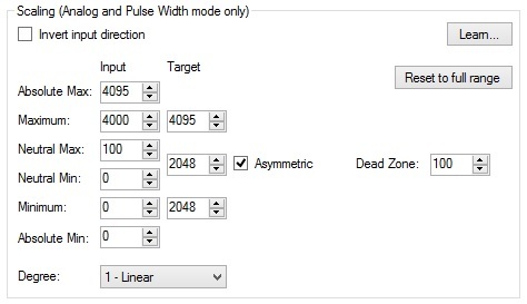
It would not make sense to try to move the target neutral value to 0 for your application (using frequency feedback). Your target should be between 2048 and the maximum that I described how to calculate in the previous paragraph. This would mean that you only want the motor to turn forward, since a value less than 2048 would cause the motor to go in reverse. The screen capture that I have attached below shows configuration settings that I used and that would probably be more applicable to your setup (although you would still need to adjust some settings). Setting the input minimum and neutral values to 0, and the target corresponding to those inputs to 2048, configures the jrk to not turn the motor (keep the number of counts per PID period to zero) when the potentiometer is turned all the way in one direction. The deadzone of 100 helps make sure the motor is completely stopped. The maximum input of 4000 refers to the maximum input from the potentiometer I used in my setup, and the maximum target of 4095 tells the jrk you want the target maximum to match the scaled feedback’s maximum (which should correspond to full speed) when the potentiometer is turned the other way. As I said before, these values might be slightly different for your system.
As for the analog to digital conversion, if you specify a number of samples to average in a PID cycle that is too short, you will see a red “yes” next to the indicator labeled “PID period exceeded” at the top of the window. You can then adjust this by increasing your PID period or decreasing the number of samples you are averaging.
-Brandon
Brandon,
Thanks for your detailed and carefully considered reply.
Without your explanation I never would have been able to configure the jrk. The explanation in the User Guide just doesn’t go far enough for me. I mean, the User Guide explanation makes sense as far as it goes but it’s not clear how to it relates to the configuration tool. I still don’t understand how configuration works but I’m going to try what you said and see what I get. I like to understand what I’m doing but I I’ll move on if I get good results. I just won’t have any idea what’s wrong or what to do if it doesn’t work.
It looks like the target values in your example range from 2048 to 4095, but your feedback values range from 2048 to 2078. I can’t see how that’s going to sum to zero at the summing junction when the motor is running at the desired speed. Don’t the target and feedback ranges have to agree? But like I said, my first priority is to get it to work even if I don’t understand it. I’ll blindly plug in numbers if I can get good results.
Apparently Pololu’s encoder terminology is not the same as with the encoders I use (usdigital.com). When usdigital says the encoder outputs 250 cpr per revolution that’s exactly how many pulses I get when I measure it. The A and B lines each produce 250 pulses per revolution. They just differ by 90 degrees in phase. I suppose encoder cpr doesn’t really doesn’t matter as far as jrk configuration is concerned. If you say your 64 cpr encoder produces 16 pulses per revolution I’ll accept that as fact and go from there.
From your explanation it seems that the number 2048 is a fixed number that represents zero speed (duty cycle). But the configuration screen allows you to change it. I don’t get it, what’s up with that?
Does the configuration you provided actually work with your 37D motor?
I hope to get back to configuring my motor tomorrow. I’ve been snowed in for two days.
thanks again!
I talked to you on the phone earlier today (after you had posted here) regarding some of these questions, but I’ll go over some of the answers again quickly, so that others can follow along.
The jrk can have a little bit of a learning curve. An important thing to remember about the jrk is that it can be used for many different applications, and within each of those applications, there are different settings and parameters that should be taken into account. It takes a little bit of time to get familiar with it and tune your settings to just the right values.
The target tells the controller what to try to set the scaled feedback to. The feedback might only be between 2048 and 2078 like in my example above, but setting the calibration in the “Feedback” tab adjusts the scaled feedback accordingly. Since my maximum is 2078, when my feedback is 2078, my scaled feedback should be 4095.
The 2048 neutral value is used in this case because of the frequency feedback mode. If you use analog or no feedback, the asymmetry option can become more important when setting your neutral value. For example, you can use it to adjust your feedback to be based on 0V to 3V instead of 0V to 5V. In your case, the asymmetry is needed so that you can prevent the motor from going in reverse. By using this asymmetry, you are able to set your neutral point at the same value as your 0V analog input. When the asymmetry box is not checked, your neutral point will default to the midpoint between your minimum and maximum, allowing the motor to spin in both directions.
The configuration I provided in my last post works with the 37D motor and analog input I am using in my test setup. Although, if I were doing this for more than a quick test, I would want to tune my PID settings more.
-Brandon
Brandon,
The 21v3 jrk is working well for my motor speed control application. It is a high quality device. I’m amazed at what it does!
Thanks for your detailed explanations. They helped me get the jrk configured. I’m still uncertain about how feedback scaling works, but your example helped a lot. The User Guide is not clear about this.
I have one recommendation that might have helped me a lot. The User Guide needs examples with actual numbers, perhaps in the appendix. Also, the User Guide describes features without explaining what they’re for. You might sell more of these if it were more obvious what the jrk’s can do. For example, the User Guide talks about capabilities that I might be useful to me but I can’t tell what they’re for, take the USB and TTL interface for example. Maybe I’ll know what the purpose of the features are if/when I actually need them.
I’m now experimenting with the jrk’s USB communication interface. I’m having some success there as well.
Good product, good support. Thanks!
Hi Brandon,
I have sent a query in relation to configuring jrk controller. I see guys able to configure and good to know that. however, i was not successful in doing so. Hope either you or some one who have configured please help.
First query: after configuring properly the feedback, the target approximately follows the scaled feedback. what is the “reasonable error”. initially, we set the proportional gain to unity and the rest I (integral) and D (derivative) are set to 0. could you please explain this.
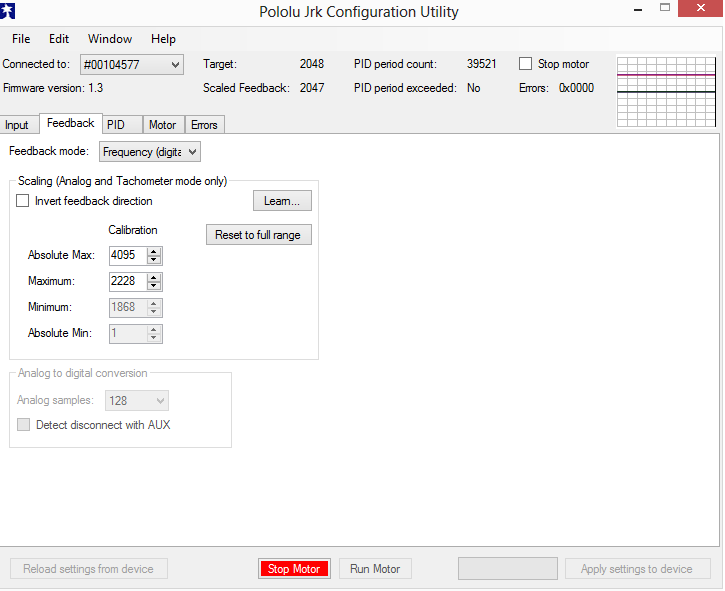
Setup i have used: E4P digital encoder - 360 counts per revolution. and at the rated voltage around 12V, i am getting 180 counts per 10 ms (~3065 rpm at the motor output).i have checked the value with arduino setup as well. so in the feedback tab i have kept the maximum as 2048+180 = 2228.
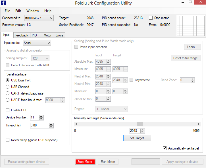
Input is serial:
Feedback setup:
output: when moved to maximum
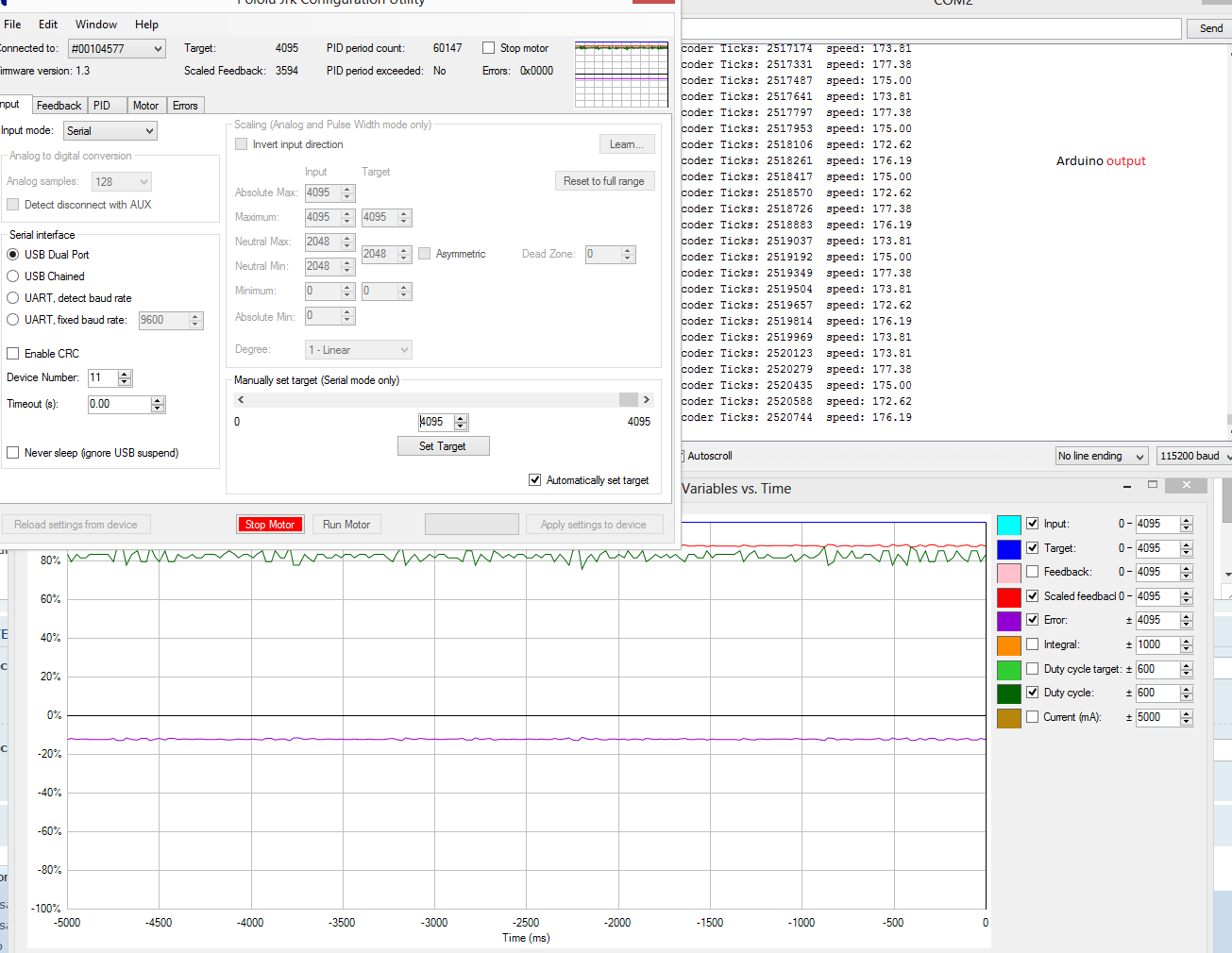
Also, when i used the default value of 4095, i see error between the serial input target and scaled feedback is ~600.
Hello.
I am not sure I understand what you are asking, but it sounds like you are concerned about the error shown in your plot. If so, you should be able to reduce this error by tuning your PID (proportional, integral, and derivative) coefficients. Typically, when using frequency feedback with the jrk the integral term is particularly important.
If that is not what you were asking, could you try rephrasing your question?
-Brandon
Hi,
Thanks for looking at.
Q1. i see other people able to configure correctly which means that target is following the input value (with only proportional value 1). i couldn’t get it and also, not sure if it is possible?
Q2. Based on my encoder counts for 10msec, could please clarify whether i have given correct values in the feedback tab. i can play with Integral to reduce the error.
Thanks.
Srinivas
You might be able to get some feedback systems to work with only the proportional coefficient set to 1; however, you will probably want to spend some time tuning your PID constants to make your system work how you want it to. Well tuned PID coefficients can result in much better performance.
Your feedback values look reasonable for your system to me.
-Brandon