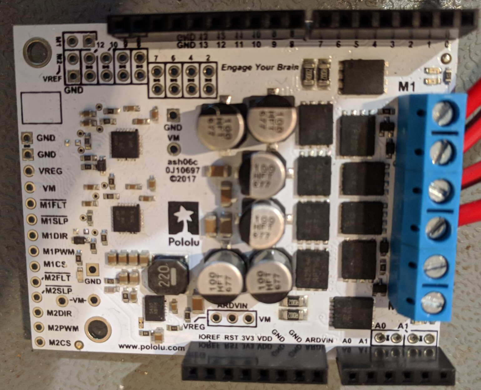
Trying to run Pololu Dual G2 High-Power Motor Driver 24v18 Shield for Arduino over a resistor (initially) using it as an arduino shield (Arduino uno)
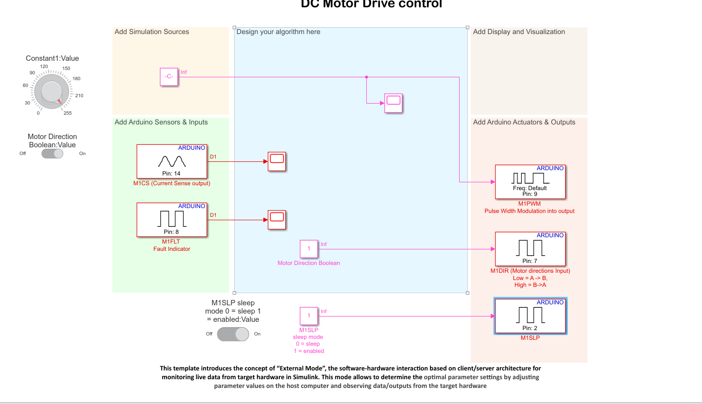
using Simulink to control the Arduino
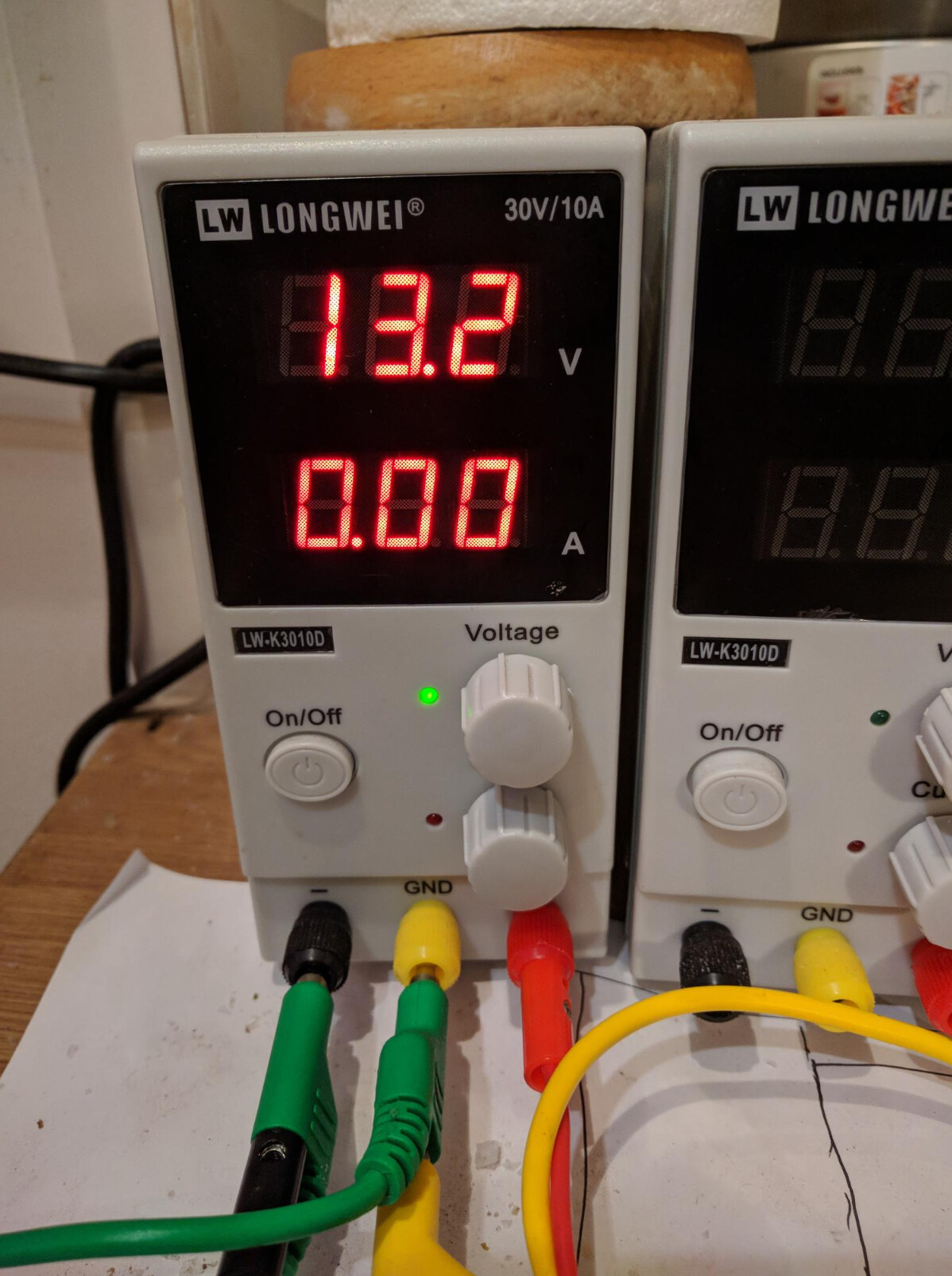
Unfortunately i am getting no current reading on my power supply when the input PWM is outputing at 5 V from the Arduino.
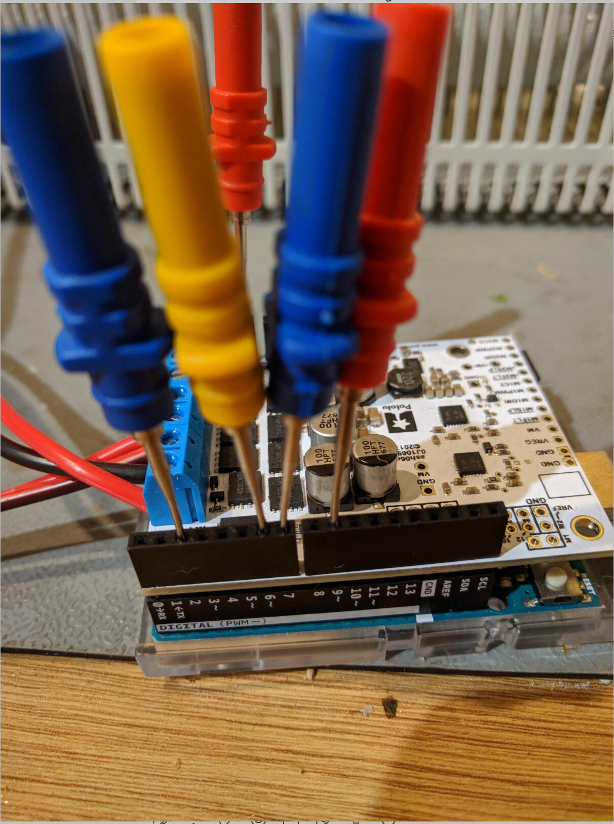
i can measure outputs on
Pin 9 - PWM arduino to board - can range the value 0-5V (Set to 5 V)
Pin7 - Motor direction - can switch 1 or 0 (set to 1)
Pin2 - motor sleep input - can switch 1 or 0 (set to 1)
can confirm that pins are working with mustimeter and reading expected value and have tried different conbinations of those values
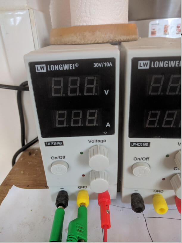
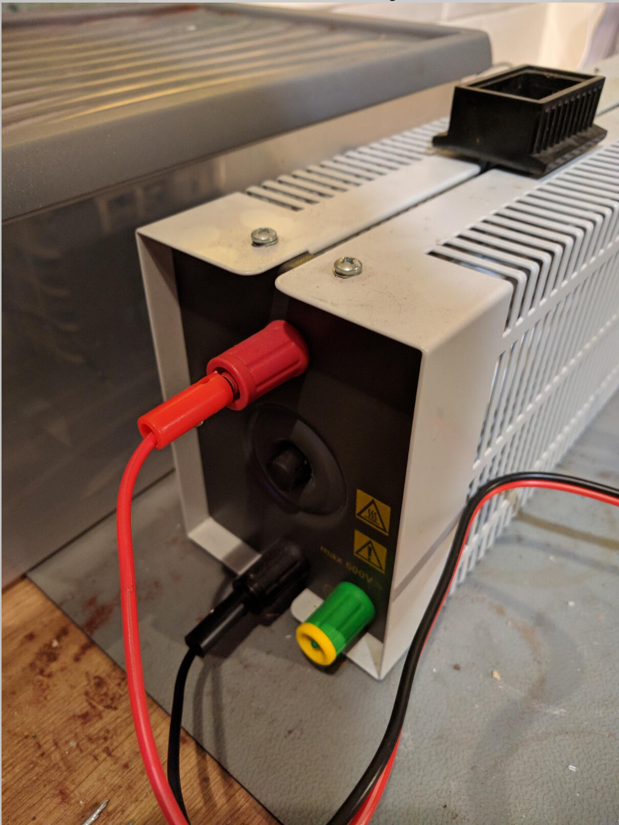
What kind of resistor are you using and what voltage are you setting the power supply to? It is hard to see your connections in your pictures with the probes in the way. Is your motor power connected to the VIN and GND terminal blocks on the short edge of the board (or are you just trying to power it through the Arduino’s VIN pin)?
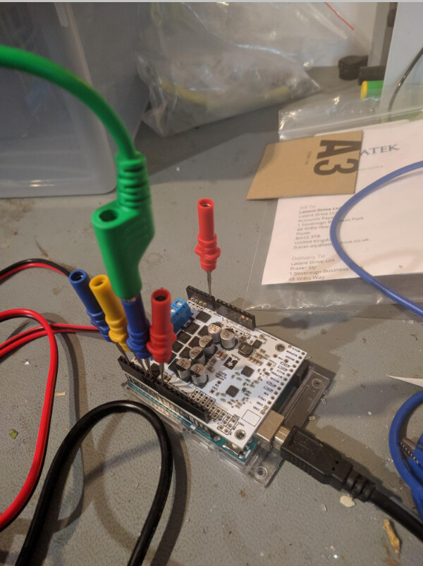
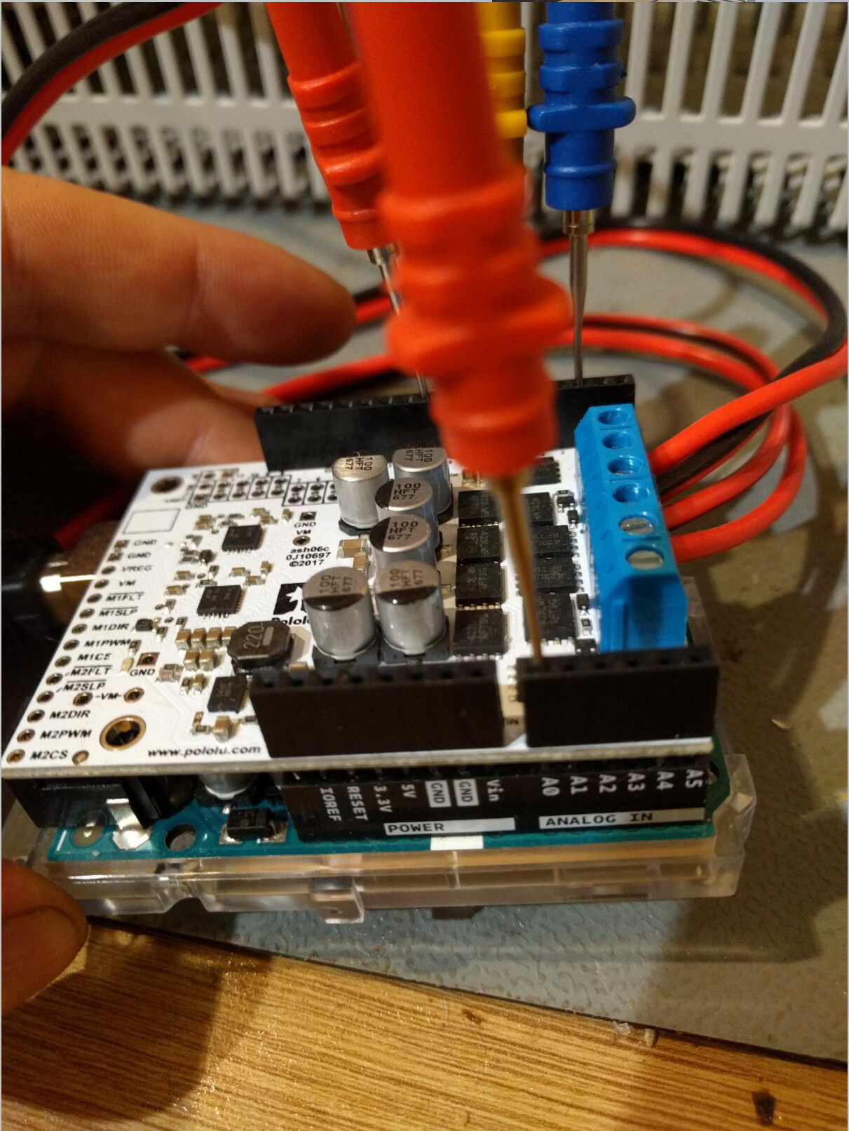
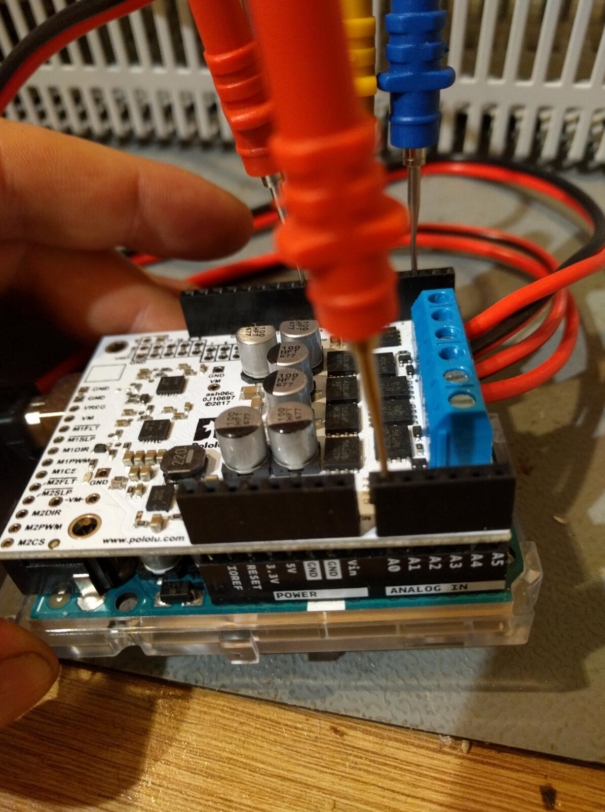
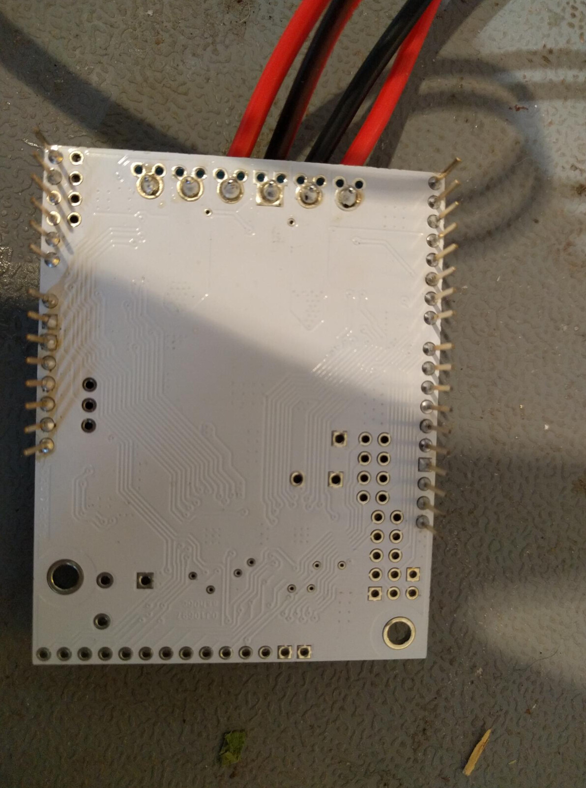
Could you post some more pictures that clearly show all of your connections (including the power supply and resistor), as well as some close-up pictures of both sides of your motor driver shield?
Thank you for the updated pictures. For future reference, you can add them in a new post instead of editing your older ones (this makes it a little easier to follow).
I didn’t notice anything obviously concerning, although it is not necessary to connect the ground and negative terminals on your power supply. Can you try the following things?
Remove the resistor from the system and measure the voltage at each M1 output.
i noticed on the images that LEDS light up on the board but could not find any references in the documentation to them. the fact that they are not lighting up atall could be a concern here
The example from the library ramps each motor channel forward then backwards in succession, so you should see some LED activity on the shield as that happens. The motor indicator LEDs for each motor channel are on either side of the terminal blocks, as indicated below:
Could you open the Serial Monitor in Arduino to see if the sketch is reporting any errors?
It does sound like it could be a connection issue, and it looks like the soldering on the terminal blocks of your motor driver shield might not be wetted very well. To test this, could you measure the voltage on the VM pin and the VREG pin on the opposite side of the board from the terminal blocks? If you aren’t getting any voltage there, you might try reflowing/touching up the solder on the terminal blocks. It is hard to tell from the angle of the picture, but it looks like the solder on the A2 and A3 pins might need some touching up too. Adafruit’s Guide to Excellent Soldering has some good references for identifying possible problem joints.