
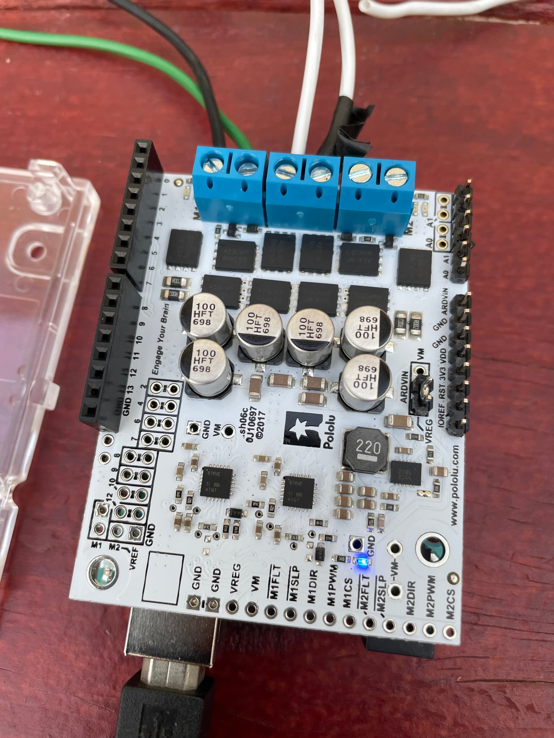
I am using Dual G2 Motor driver and I see the GND LED glow(as attached), and there is no current to motor. Can you help with what the GND LED is for?( also where do I find specs for such things, I didnt see any in the manual) Also, I was able to run the motor earlier with the same connections.
Hello.
I moved your post to its own thread since it seemed different enough to warrant its own topic.
The LED you are referring to is a power indicator LED that is tied to the output of the onboard regulator (the GND label is for the through-hole next to it).
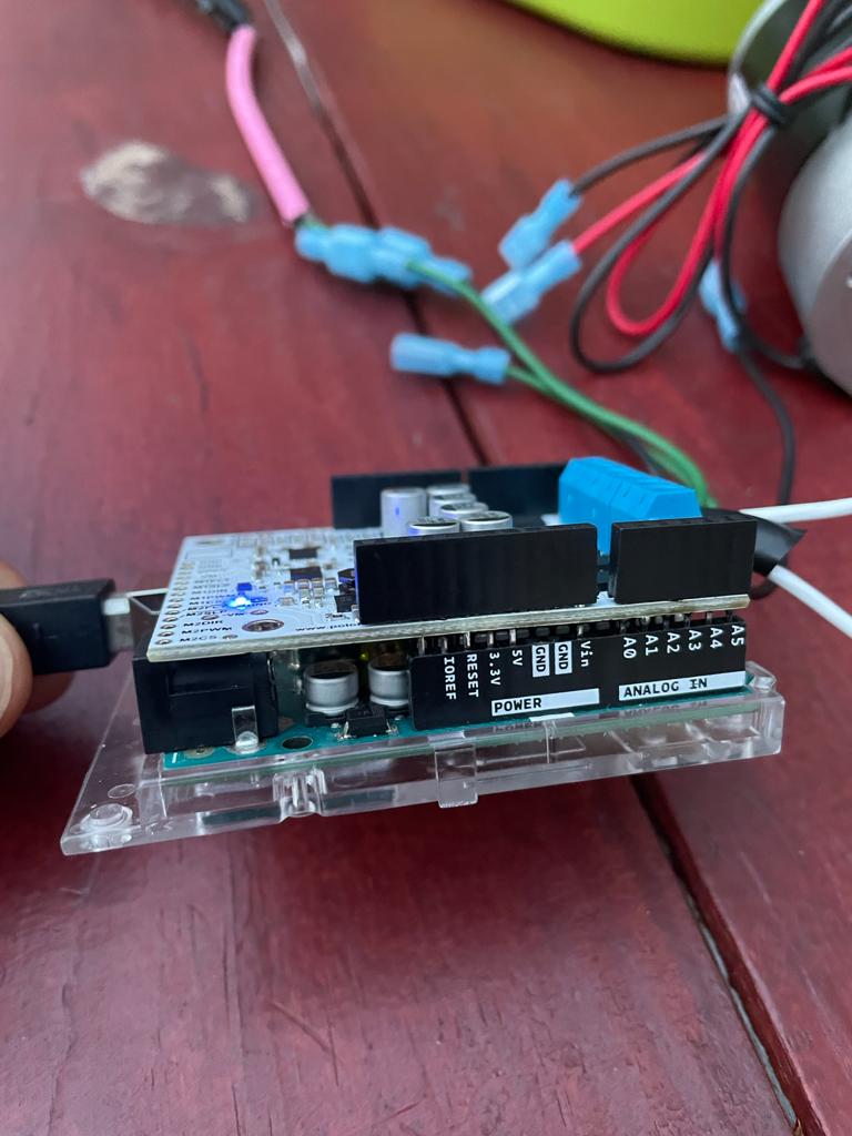
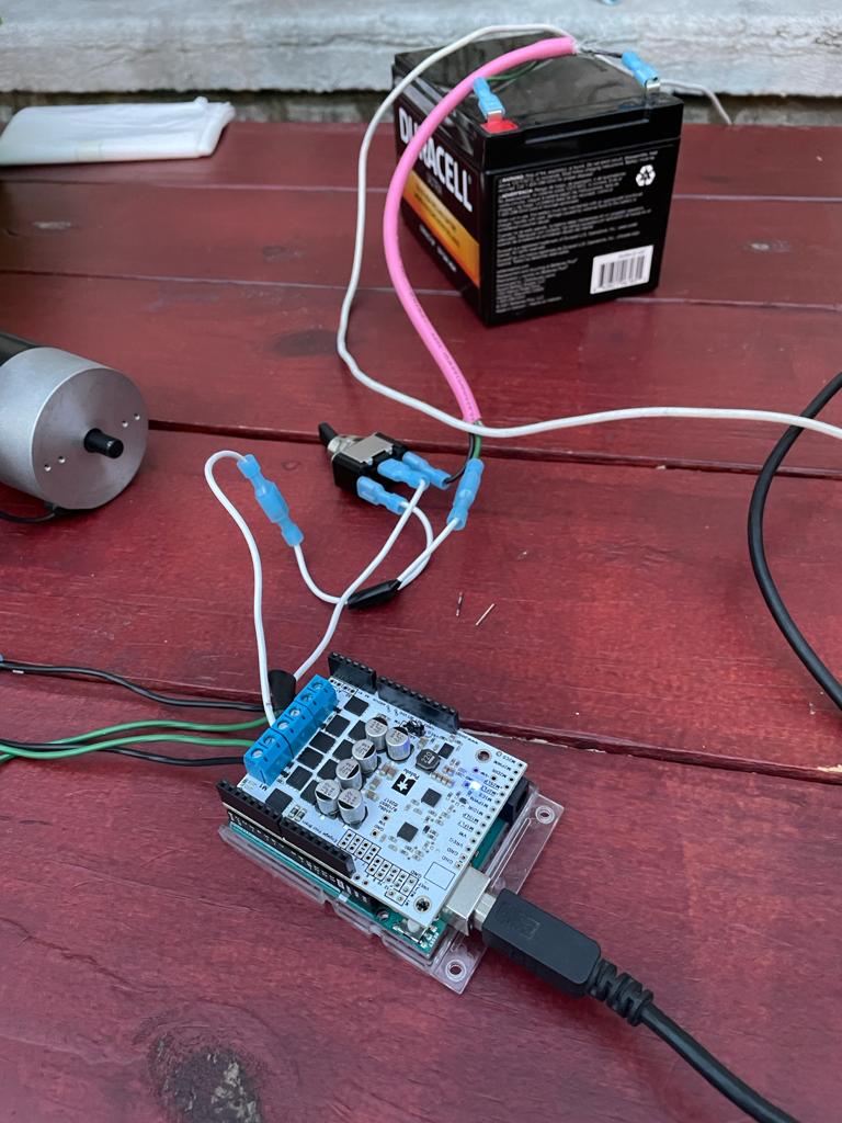
Can you post pictures showing your entire system, including all of your connections, as well as close-up pictures of the underside of the driver shield so we can see the soldering? Also, can you post more details about your setup, such as what power supply, motor, and code you are using?
Brandon
Thanks for the response Brandon.
Earlier I saw serial monitor was sending out PWM, but LEDs by motor terminals do not glow, and no current on motor pins.
But, now I get motor fault and program exited. Can I know what it means to fault?
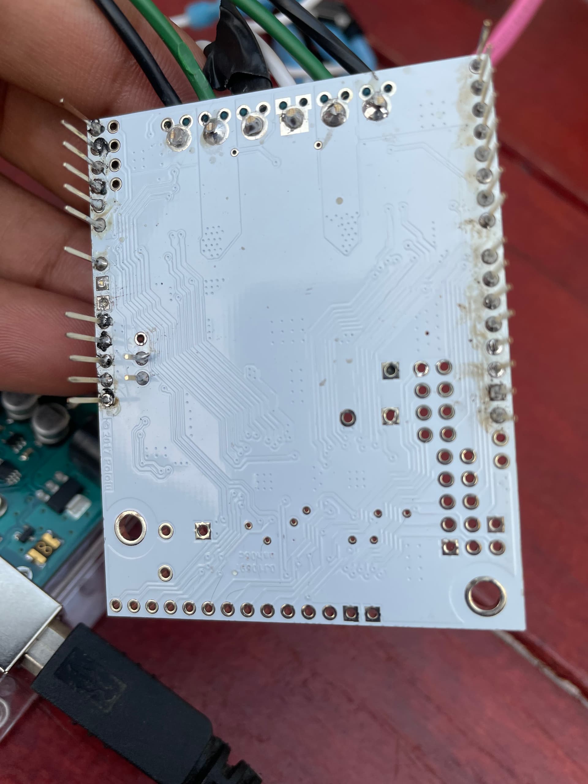
Attached is reverse side image of shield.
I am running demo code. And here is my serial monitor O/P:
19:01:32.151 → ⸮⸮⸮Dual G2 High Power Motor Shield
19:01:33.755 → M1 fault
Note: I had mistakes while soldering, so had to desolder and solder back. In the process, 2 of the 3 ground pins couldnt be recovered.
Setup :
12V Battery for supply
Motor: Amp Flow P40-250 ( I ran this motor with this same shield earlier)
Code : Demo example from library
I see supply voltage(~13V) across shields supply pins.
The motor driver can detect several fault states indicated by the FLT pin being driven low. The faults include short circuits on the outputs, under-voltage, and over-temperature. Do you still get fault conditions if you run the demo code without your motors attached (you can still get an indication of the outputs by looking at the indicator LEDs on either side of the terminal blocks)?
It looks like several of your solder joints might not be properly wetted to the pads on the board; an intermittent connection could cause erratic problems that are hard to diagnose, so I recommend trying to re-work those. In particular, you should double check the soldering on the pins that the shield uses (i.e. pins 2, 4, 6, 7, 8, 9, 10, 12, A0, and A1), as well as the terminal blocks.
By the way, are you sure your power switch is connected properly? Usually a switch would be in-line with 1 power wire between the board and the battery (not both of them).
Brandon
Brandon, I got a new shield and redid the soldering( I think its clean this time- attached). I am running demo and see LEDs glow for clockwise, anti-clock direction, but the the motors donot run. There is no current in the motor terminals. I see voltage on motor pins though. Motors are okay, as I tested them by connecting to power directly. I kept all my connections same as in earlier pictures. Is there a default current limit which might be kicking in?
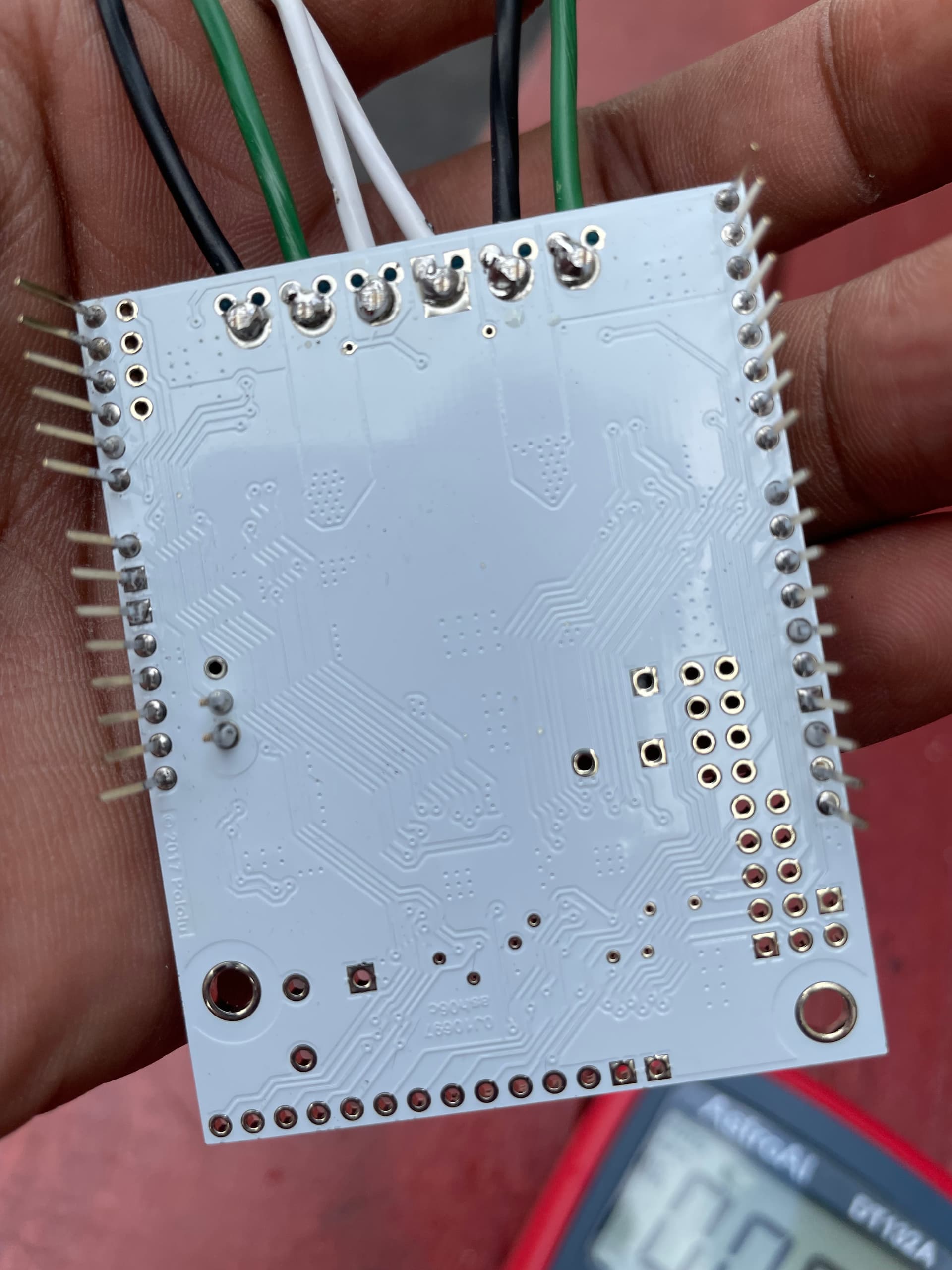
The first thing I noticed is that the soldering on the terminal block pins are not wetting to the board very well. It looks like not enough heat was applied; since those are larger pins and larger pads on the board, they take more heat than the smaller 0.1" pins. So, you should rework those pins before trying to troubleshoot anything else.
If that doesn’t fix the problem, can you post updated pictures of your soldering as well as more information about your setup? What are the specifications of your motor? The default threshold for the active current limit feature is set to 60A, which should be well above what an appropriately sized motor would draw.
Brandon
Thanks Brandon. It worked after I added more soldering metal to terminal pins.
1 Like