Hi
I have a Pololu VNH5019 connected to a Arduino Uno. All the motor controls work fine until I attach a servo to pin 3 (or to other pins). I tried the “myservo”-library and the “servo”-library. With both the motors don’t repsond to the incoming commands. According to the Pololu schematic, the pin 3 is not used for communication between the shield and the Uno.
The code (partial):
#include <Servo.h>
#include <SoftwareSerial.h>
#include "DualVNH5019MotorShield.h"
DualVNH5019MotorShield md;
Servo Servo1; //create servo project

int command = 0;  //incoming serial data
int led = 11;
int ledPin = 13;
int buttonpin = 5;
int servoPin = 3;
SoftwareSerial bluetooth(A2, A3);
int cmd;

Servo head;
void setup() {
  bluetooth.begin(9600);
  Serial.begin(9600); // set up Serial library at 9600 bps - this is the speed the serial interface will work all
  pinMode(led, OUTPUT); //connect here the blue LED
  pinMode (ledPin, OUTPUT);
  pinMode (buttonpin, OUTPUT);
  md.init();
  Servo1.attach(servoPin);

}

void loop() {

  if (bluetooth.available()) {
    cmd = bluetooth.read();
    Serial.write(cmd);

    switch (cmd)
    {
      case 'C':
        md.setM1Speed(0); // stopped
        md.setM2Speed(0); // stopped
        break;

      case 'A':
        md.setM1Speed(-300);
        md.setM2Speed(-300);
        break;
Hello.
The dual VNH5019 motor shield Arduino library assumes PWM is on Timer 1, so any other libraries that also use Timer 1 (like the Arduino servo library) will conflict. One way to get around this is to try using some of the code in our Zumo Robot for Arduino user’s guide, which also assumes PWM is on Timer 1 and shows how to control a single servo using Timer 2. If you decide to use some of that code and have trouble implementing it, let me know specifically what code you have tried and how your system behaves, and I can try to help.
-Jon
Hi Jonathan
Thanks for your reply! I plan to do it like you proposed, but do I have to implement all of this?
// This line specifies what pin we will use for sending the
// signal to the servo.  You can change this.
#define SERVO_PIN 11

// This is the time since the last rising edge in units of 0.5us.
uint16_t volatile servoTime = 0;

// This is the pulse width we want in units of 0.5us.
uint16_t volatile servoHighTime = 3000;

// This is true if the servo pin is currently high.
boolean volatile servoHigh = false;

void setup()
{
  servoInit();
}

void loop()
{
  servoSetPosition(1000);  // Send 1000us pulses.
  delay(1000);
  servoSetPosition(2000);  // Send 2000us pulses.
  delay(1000);
}

// This ISR runs after Timer 2 reaches OCR2A and resets.
// In this ISR, we set OCR2A in order to schedule when the next
// interrupt will happen.
// Generally we will set OCR2A to 255 so that we have an
// interrupt every 128 us, but the first two interrupt intervals
// after the rising edge will be smaller so we can achieve
// the desired pulse width.
ISR(TIMER2_COMPA_vect)
{
  // The time that passed since the last interrupt is OCR2A + 1
  // because the timer value will equal OCR2A before going to 0.
  servoTime += OCR2A + 1;

  static uint16_t highTimeCopy = 3000;
  static uint8_t interruptCount = 0;

  if(servoHigh)
  {
    if(++interruptCount == 2)
    {
      OCR2A = 255;
    }

    // The servo pin is currently high.
    // Check to see if is time for a falling edge.
    // Note: We could == instead of >=.
    if(servoTime >= highTimeCopy)
    {
      // The pin has been high enough, so do a falling edge.
      digitalWrite(SERVO_PIN, LOW);
      servoHigh = false;
      interruptCount = 0;
    }
  }
  else
  {
    // The servo pin is currently low.

    if(servoTime >= 40000)
    {
      // We've hit the end of the period (20 ms),
      // so do a rising edge.
      highTimeCopy = servoHighTime;
      digitalWrite(SERVO_PIN, HIGH);
      servoHigh = true;
      servoTime = 0;
      interruptCount = 0;
      OCR2A = ((highTimeCopy % 256) + 256)/2 - 1;
    }
  }
}

void servoInit()
{
  digitalWrite(SERVO_PIN, LOW);
  pinMode(SERVO_PIN, OUTPUT);

  // Turn on CTC mode.  Timer 2 will count up to OCR2A, then
  // reset to 0 and cause an interrupt.
  TCCR2A = (1 << WGM21);
  // Set a 1:8 prescaler.  This gives us 0.5us resolution.
  TCCR2B = (1 << CS21);

  // Put the timer in a good default state.
  TCNT2 = 0;
  OCR2A = 255;

  TIMSK2 |= (1 << OCIE2A);  // Enable timer compare interrupt.
  sei();   // Enable interrupts.
}

void servoSetPosition(uint16_t highTimeMicroseconds)
{
  TIMSK2 &= ~(1 << OCIE2A); // disable timer compare interrupt
  servoHighTime = highTimeMicroseconds * 2;
  TIMSK2 |= (1 << OCIE2A); // enable timer compare interrupt
}
Some more info for you:
My servo has only to be moved in to five positions (0, 45, 90, 135 and 180 degrees) which are stated in a switch cmd.
Thanks for your help!
Best regards, Laurin
Yes, you should paste all of that code into your sketch except for the loop() function. loop() has two examples of how to use the servoSetPosition() function, which is a useful command that you will probably want to use inside your switch case.
-Jon
Hi Jonathan
I tried to implement the code (as you proposed without the loop and with the “servoSetPosition”-function. But unfortunately as soon as I connect the servo PWM-line of the servo to Pin 3, all conrols are down.
Here is my actual code:
#include <Servo.h>
#include <SoftwareSerial.h>
#include "DualVNH5019MotorShield.h"
DualVNH5019MotorShield md;

int command = 0;  //incoming serial data
int led = 11;
int ledPin = 13;
int buttonpin = 5;
SoftwareSerial bluetooth(A2, A3);
int cmd;
#define SERVO_PIN 3
uint16_t volatile servoTime = 0;
uint16_t volatile servoHighTime = 3000;
boolean volatile servoHigh = false;

Servo head;
void setup() {
  bluetooth.begin(9600);
  Serial.begin(9600); // set up Serial library at 9600 bps - this is the speed the serial interface will work all
  pinMode(led, OUTPUT); //connect here the blue LED
  pinMode (ledPin, OUTPUT);
  pinMode (buttonpin, OUTPUT);
  md.init();
  servoInit();

}

// This ISR runs after Timer 2 reaches OCR2A and resets.
// In this ISR, we set OCR2A in order to schedule when the next
// interrupt will happen.
// Generally we will set OCR2A to 255 so that we have an
// interrupt every 128 us, but the first two interrupt intervals
// after the rising edge will be smaller so we can achieve
// the desired pulse width.
ISR(TIMER2_COMPA_vect)
{
  // The time that passed since the last interrupt is OCR2A + 1
  // because the timer value will equal OCR2A before going to 0.
  servoTime += OCR2A + 1;

  static uint16_t highTimeCopy = 3000;
  static uint8_t interruptCount = 0;

  if(servoHigh)
  {
    if(++interruptCount == 2)
    {
      OCR2A = 255;
    }

    // The servo pin is currently high.
    // Check to see if is time for a falling edge.
    // Note: We could == instead of >=.
    if(servoTime >= highTimeCopy)
    {
      // The pin has been high enough, so do a falling edge.
      digitalWrite(SERVO_PIN, LOW);
      servoHigh = false;
      interruptCount = 0;
    }
  }
  else
  {
    // The servo pin is currently low.

    if(servoTime >= 40000)
    {
      // We've hit the end of the period (20 ms),
      // so do a rising edge.
      highTimeCopy = servoHighTime;
      digitalWrite(SERVO_PIN, HIGH);
      servoHigh = true;
      servoTime = 0;
      interruptCount = 0;
      OCR2A = ((highTimeCopy % 256) + 256)/2 - 1;
    }
  }
}

void servoInit()
{
  digitalWrite(SERVO_PIN, LOW);
  pinMode(SERVO_PIN, OUTPUT);

  // Turn on CTC mode.  Timer 2 will count up to OCR2A, then
  // reset to 0 and cause an interrupt.
  TCCR2A = (1 << WGM21);
  // Set a 1:8 prescaler.  This gives us 0.5us resolution.
  TCCR2B = (1 << CS21);

  // Put the timer in a good default state.
  TCNT2 = 0;
  OCR2A = 255;

  TIMSK2 |= (1 << OCIE2A);  // Enable timer compare interrupt.
  sei();   // Enable interrupts.
}

void servoSetPosition(uint16_t highTimeMicroseconds)
{
  TIMSK2 &= ~(1 << OCIE2A); // disable timer compare interrupt
  servoHighTime = highTimeMicroseconds * 2;
  TIMSK2 |= (1 << OCIE2A); // enable timer compare interrupt
}


void loop() {

  if (bluetooth.available()) {
    cmd = bluetooth.read();
    Serial.write(cmd);

    switch (cmd)
    {
      case 'C':
        md.setM1Speed(0); // stopped
        md.setM2Speed(0); // stopped
        break;

      case 'A':
        md.setM1Speed(-300);
        md.setM2Speed(-300);
        break;

      case 'B':
        md.setM1Speed(-120);
        md.setM2Speed(-120);
        break;

      case 'D':
        md.setM1Speed(120);
        md.setM2Speed(150);
        break;

      case 'E':
        md.setM1Speed(380);
        md.setM2Speed(400);
        break;

      case 'F':
        md.setM1Speed(250);
        md.setM2Speed(-250);
        break;

      case 'G':
        md.setM1Speed(120);
        md.setM2Speed(-120);
        break;

      case 'H':
        md.setM1Speed(-120);
        md.setM2Speed(120);
        break;

      case 'I':
        md.setM1Speed(-250);
        md.setM2Speed(250);
        break;

      case 'J':
        digitalWrite(ledPin, HIGH);
        break;

      case 'K':
         digitalWrite(ledPin, LOW);
         break;

      case 'L':
         digitalWrite(buttonpin, HIGH);
         break;

      case 'M':
         digitalWrite(buttonpin, LOW);
         break;

       default:
        cmd=0;
        break;

      //Servo

      case 'N':
         servoSetPosition(500);
         break;

      case 'O':
          servoSetPosition(1000);
          break;

      case 'P':
          servoSetPosition(1500);
          break;

      case 'Q':
          servoSetPosition(2000);
          break;

      case 'R':
          servoSetPosition(2500);
          break;

      //IR LED

      case '0':
          digitalWrite(led, LOW);
          break;
      case '1':
           analogWrite(led, 50);
           break;
      case '2':
           analogWrite(led, 100);
           break;
      case '3':
           analogWrite(led, 150);
           break;
      case '4':
           analogWrite(led, 200);
           break;
      case '5':
           analogWrite(led, 255);
           break;


   }

  }
}
It is not entirely clear what is happening in your setup when you say “all conrols are down”. What specifically are you seeing? Also, it sounds like you are saying that you notice this behavior as you connect the signal wire of your servo to pin 3 on the Uno. Is that correct?
As for your code, I did not notice anything obviously wrong. Can you tell me more about your setup? How are you supplying power? Can you link to a product page or datasheet for the servo you are using? Can you also send pictures that clearly show the connections between your Uno + VNH5019 shield, your servo, and power?
By the way, you should not need #include <Servo.h> and Servo head anymore, so you can remove those two lines from your code.
-Jon
Hi Jonathan,
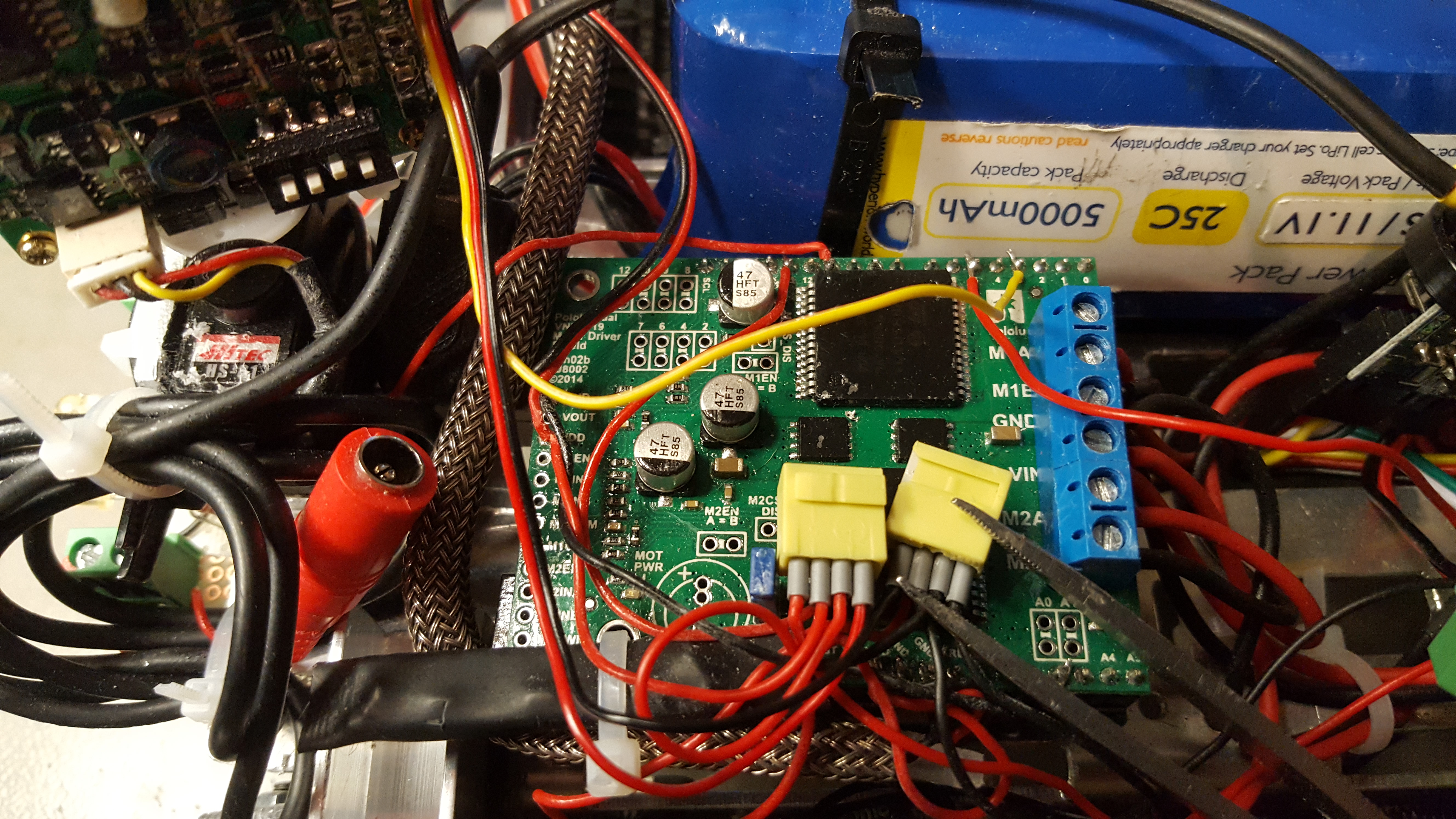
Thanks once again for your answer! I’m sorry about the missleading expression “all controls are down”. I found out today, that the connection between the arduino uno and the vnh5019 was not OK (to answer an of your quetsions: the vnh5019 is plugged onto the arduino uno with the standard headers). This is why there were no reactions to my commands. Now what I’m seeing is a servo which moves around nercously, no matter if I send commands or not.
The servo is a “HiTec HS81” (standard RC-servo) and is powered by the 5V source (small yellow clamps) of the uno/vnh5019 (see picture). I connected my digital oscilloscope to pin 3 and I saw 5v-pulses.
Hey wild_at_heart, not sure if this will help, but I had a similar issue and got great advice from DrGFreeman in this thread:
Servos and motors: A-Star 32U4 Robot Controller SV with Raspberry Pi Bridge
Basic tl;dr was that you can create a copied library to use another timer when you want to use both motors and a servo
Hi coyotlgw
Thanks for your post! I just tried the ServoT3-library, but unfortunately my servo still doesn’t work. Did you include the “ServoT3.h” and the “servo.h” or just the first?
Thank you kindly.
wild_at_heart
@wild_at_heart: It sounds like you might be describing servo jitter, where the servo shakes or vibrates, sometimes intermittently, and does not seem to directly respond to input signals. What kind of load is on the output on your servo? If you remove the load, does the servo still behave the same? Is the servo’s 5V source the Arduino Uno’s 5V pin?
-Jon
Yes it seems that I have a servo jitter. There’s no big load on the servo. It only has a small camera mounted on. I’m pretty sure that the load is not an issue. Yes the source is the arduino uno’s 5V pin.
It sounds like you have a power issue: the Arduino’s 5V pin cannot provide much current, and it looks like the amount of current your servo needs (even with such a light load) is more than that pin can handle. So, the jitter you are getting is from the Arduino’s onboard 5V regulator trying to protect itself by cutting in and out of supplying current. For your servo, I recommend using a supply that can handle around 1.5A or more.
-Jon
Hey Jonathan, I changed my 5V power supply in the meantime. Now I have a 2A-Regulator. But that didn’t solve the problem. But what I found by printing (Serial.Print) to the serial monitor before the switch cmd (on the receiver side) could be the problems cause. Instead of just sending the characters I get this:
0 (which is the angle 0 for the servo, OK)
C67 (“C” is for all motors stopp, OK but why “67”?)
K75 (“K” is for ledPin low, OK, but why numbers again?)
M77 (“M” is for ButtonPin low, OK, but again numbers)
and so on…
So this would explain why the servo is very rapidly shackying. He’s shacking between 67, 75 and 77 degrees 
Here is the current sketch for the transmitter (arduino mini pro):
TX_433Mhz_Robot_SepVer.ino (1.8 KB)
Do you know why my transmitter sends these numbers?
In your main loop() function, I noticed you have BTserial.write(val);, which occurs just prior to all of your conditional statements. From the rest of your code, it looks like you only intend to use letters with BTserial.write(), and BTserial.write(val); will write the value of val, which looks like it will be a number between 0 and 180. Removing that line of code might fix things. If it does not, can you also post the code that interprets your custom commands and controls the servo and VNH5019?
-Jon
Yes, my plan is to be able to control the servo without steps (0-180 degrees) in the end. In the meantime I changed the code to test the servo without the other controls (motors and switches). I wanted to see whether I can control the servo by sending the angle (0-180 degrees). But strangely I get very odd numbers and characters (“´1”, “Œ1” …) on the serial monitor (Serial.Print after bluetooth.read) on the receiver side.
Here are the codes that I used:
Transmitter:
TX_433Mhz_Robot_SepVer_Temp.ino (645 Bytes)
Receiver:
RX_433Mhz_Robot_SepVer_Main.ino (2.6 KB)
I see two issues with your serial debugging code. First, Serial.println(bluetooth); is trying to print the value of bluetooth which is an instance of SoftwareSerial; what this ends up doing is converting the SoftwareSerial object to a boolean value (indicating that the serial port is available) and printing the boolean as “1”. I suspect that information is not what you want to print. Second, Serial.write(cmd); should be Serial.print(cmd);. Serial.write() will send the raw binary value of cmd to the serial port, which the serial monitor is (wrongly) interpreting as an ASCII character, which is why you are seeing those strange characters. Using Serial.print() will send the appropriate ASCII representation of cmd to the serial port so that you can read it. Additionally, you might also double check that the serial monitor’s baud rate is set to the same baud rate you are using in your sketches (9600).
I do not see any code that controls a servo in your sketches, but to try to address the issue of servo jitter, I recommend you simplify your system and try controlling your servo directly from an RC receiver while supplying power to it from your new 2A regulator. If the servo does not jitter in that setup, then I no longer suspect a power issue, and the issue is most likely code related.
-Jon
Hi Jon
I realized that it was wrong to print “bluetooth”. Of course I have to print “cmd”. Why you don’t see any code which controls the servo is the following: In order to get rid of the timer-problem I took a arduino mini board that I had and uploaded the servo code there. I connected the board together with the arduino uno to the RX of the rf-module. I tried different codes (with angle degrees and cases with fixed angles) but the servo would behave strange as always (I don’t think it’s a hardware problem) all the time. Today I uploaded a standard sweep sketch which sweeps the servo from 0 to 180 and back. This works fine - the servo does not jitter at all. I really just don’t know why it’s so difficult to control a single servo. I think I’ve come to the conclusion that I’m not able to control the servo with my setting. I believe it should be done with a protocol for all controls, but this is just to challenging to program for me at this point.
In general, controlling servos without jitter can be difficult since it is very timing dependent and if your microcontroller is handling other events at the same time it could get thrown off. To simplify your code and help the jitter, you might consider adding a dedicated servo controller like one of our Maestro servo controllers. In particular, if you only want to control a single servo, the 6-channel Maestro would the most reasonable choice of controller, since it has the fewest channels. Also, we have an Arduino library for them, which would make getting started easier.
-Jon