I have the “Pololu Jrk 21v3 USB Motor Controller with Feedback (Fully Assembled)” wired up and drivers and Jrk Configuration Utility software installed and can successfully run the Pololu (item #: 1442) motor but with only the “Analog Voltage” feedback option. i read the “Pololu jrk’s Motor Controller User’s Guide” [many times] but there is little information on how to actually setup the “Frequency (digital)” feedback option. [I beilieve i have it wired correctly: Yellow wire from motor encoder (A output) connected to controller’s “FB” input pin; and green wire from motor encoder (“GND”) to “GND” input pin on controller (two pins from FB pin) - is this wiring correct for “Frequency (digital)” feedback option?] Are there examples or other documentation somewhere showing the use of the frequency (digital) feedback option as applied to the motor i am using (item #: 1442), or similar, and associated/typical settings for the “Feedback”, “PID”, and “Motor” tabs in the config utility program? Currently, i have only set the Proportional coeff = 1, other 2 coeffs are = 0. Have other customers been successful with applying the Frequency (Digital) feedback option with this motor and controller combo ? Am i missing something? Help ! 
thanks for any additional guidance and assistance,
John
Hello, John.
It sounds like your wiring might be correct. You can also power the encoder board through the blue wire by connecting it to one of the 5V output pins on the jrk (if you are not already powering it from a separate 5V source).
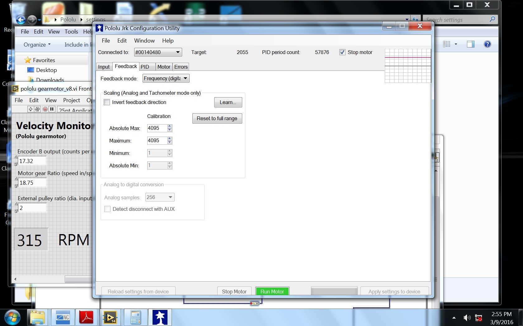
When using frequency feedback, you will probably want to adjust your feedback scaling in the “Feedback” tab of the Jrk Configuration Utility. To calculate what the “Maximum” should be, it helps to understand how the frequency feedback works. The feedback is reported as 2048 + n (where n is the number of pulses measured in a single PID cycle). Note that since the feedback value must be between 0 and 4095, the jrk can measure a maximum of 2047 pulses in a single PID period; you can modify the PID period in the “PID” tab of the Jrk Configuration Utility. You should be able to determine the maximum pulses you expect to receive from your encoder since you know the approximate RPM of the motor and the PID period.
Once you have your feedback scaling set, you can check it by using the pull-out plot of variables vs time, and making sure the “Scaled feedback” variable changes from 50% when the motor is stopped to 100% when the motor is going full speed in one direction and down to 0% when it is going full speed in the opposite direction.
I am not sure of what PID coefficients might work well with that particular motor, when using frequency feedback with the jrk the integral term is particularly important. It might take some trial and error to get the PID coefficients tuned well. You can use the same plot of variables vs time to graph the error, or compare the scaled feedback to the target, while you are adjusting the terms.
There is some additional information (such as an example of calculating the maximum pulses per PID period) that you might find helpful in this thread. The original question in that post is about controlling the motor speed in a single direction, but a lot of the explanations still apply to your case.
-Brandon
ok Brandon, thanks for your reply!
i will try adjusting my feedback scaling per your guidance and referenced thread.
do you have a guesstimate as to what i should start with as an entry for the Integral coefficient? my current P coeff is = 1.0, D coeff = 0.0.
-john 
I do not have a particular value to suggest as a starting point, but I would generally recommend trying to get the error as close to zero as you can using only the proportional term first. Then, you can try increasing the integral term in steps to get the error much lower. You can monitor the impact of the changes you are making using the plot of variables vs time that I mentioned in my previous post.
-Brandon
Hi Brandon,
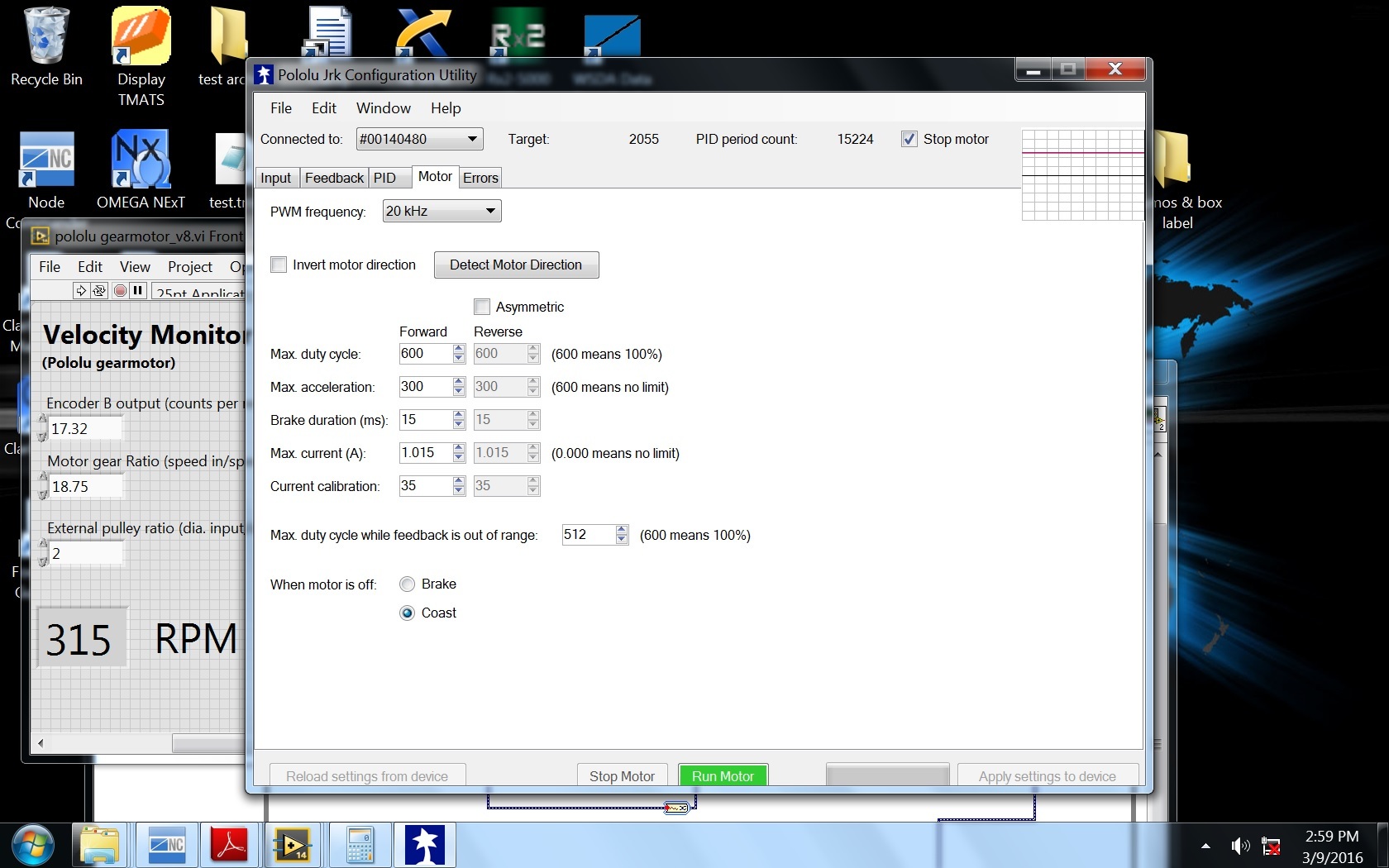
Great News !!!  I got motor running at the target i specified (in the Input, serial tab). Settings that i ‘tweaked-in’ were P=10; I=1.25; D=0.0…utilizing the frequency digital feedback option…see attached screensave.
some more q’s:
- what does the “Automatic” option w/in the Input, serial tab do when inputting the target value?
- if i’m undershooting or overshooting my target by about 5-10 RPM, how can i get it more accurate? I never did understand the scaling in the feedback tab and just selected “Reset to full range” or 4095 for both Absolute Max and Max values…see attached screensave. Is there any variable in the Motor tab to adjust to reduce the undershooting/overshooting (see attached screensave) ?
Can i increase my PID period to 100 ms, from 10 ms, to increase resolution of target setting in order to reduce this undershooting/overshooting ? Currently - at 10 ms, my counts are 16 from FB, so 2048 + 16, or 2064, which results in about 612 RPM, but i need more like 600 RPM. If i set target at 2063, i undershoot to about 590 RPM. Alternatively, if i change PID period to 100 ms, my counts will be 160 from FB, so 2048 + 160, or 2208 - will this allow me the resolution i need to fine-tune to 600 RPM, i.e., subsequent fine-tuning target to 2200 may get me closer to 600 RPM ?
thanks for all your help,
John
If you are referring to the “Automatically set target” check box, it makes the “Manually set target” slider automatically update the target position when moved. When the box is not checked, moving the slider will not update the target position until you click the “Set Target” button.
From the way you describe the overshoot and undershoot that you are seeing, it sounds like you are actually referring to steady state error. If that is the case, you might need to continue adjusting your PID coefficients. Increasing the PID period might give you more resolution in your target values; however, keep in mind that there are drawbacks to doing this. Increasing the PID period will lower the rate that corrections are made by the system, which could result in more overshoot or even instability if the PID period is too long. Also, note that you might need to adjust your PID coefficients when the PID period is changed. If you want to try increasing the PID period, I would recommend increasing it in small increments (maybe 5ms at a time).
As for the feedback scaling, you mentioned getting 16 counts at full speed when the PID period is 10ms; this would mean that your maximum can be set to around 2064. Please note that if you increase the PID period, you should adjust this as well. For example, if you get 16 counts in 10ms, you will probably get around 32 counts in 20ms, so the maximum can be set to around to 2080. Configuring the scaled feedback should help make the system response smoother, but like changing the PID period, you will likely need to adjust your PID coefficients. The absolute maximum setting is used as a threshold for triggering the feedback disconnect error, so you can set this to something safely higher than the configured maximum.
-Brandon
thanks Brandon - i will try your suggestions! Excellant tech support !!!
-john