Firstly, apologies for my lack of knowledge but robotics is a new hobby.
I’ve got the jrk 21v3 linked to a linear actuator with analog feedback being controlled by a Spektrum DX2E. I went through the user manual for hook-ups and the config. utility.
Settings file is attached.
I can’t for the life of me get the remote to move the actuator, even without feedback enabled, and the plot of the input is constant at 100% despite the actual controller position. Did I miss reading a critical section?
Also, is it possible to include an auto-zero functionality without having the reprogram the chipset? I have the necessary software but have no experience with anything outside VBA 
Thanks in advance!
jrk_21v3_settings.txt (1.39 KB)
Hello.
Your settings file shows the input mode set to “analog”. You should have it set to “pulse” since you are using a pulse width input from an RC receiver. Could you try changing that and seeing if it is the only problem? If that does not fix the problem, could you remove the Spektrum DX2E from your system and make sure the actuator responds when you control it directly from the Pololu Jrk Configuration Utility software?
Also, it is unclear to me what you are asking regarding auto-zero functionality; could you explain what you want the jrk to do?
-Brandon
Brandon,
Thanks for your quick reply! Oddly, setting the input to pulse width returns an ‘input disconnect’ error, but I can control the actuator when in serial mode via the software as currently set up. Also, I do get voltages of .3 to .6 V from the receiver input line
The goal is to control the motion of the actuator by remote control with the target for the midpoint of the r/c input being the midpoint of the actuator stroke. Where once the remote control is returned to it’s neutral position, so does the actuator… which typing that out I now realize is exactly what the micro-controller is for! There are stupid questions!! 
I did modify the settings by ‘learning’ the input and feedback extents, which I realize I should have done initially.
(new attached settings file) ← in serial mode so i could retract the actuator.
I’ll try removing the r/c components, but maybe just some PID tuning?
Thanks again!
NEW_jrk_21v3_settings.txt (1.39 KB)
I suspect that the problem might be from your setup. Could you post a picture of your setup, along with a diagram of your connections? Since your are not getting a response to your RC signal, you might try simplifying your setup by removing the feedback and any PID settings until you can get it to respond.
Also, did you measure the signal line from your receiver with a multimeter to get that 0.3V to 0.6V reading? If you have access to an oscilloscope, it would give you a much more accurate reading from a PWM signal.
-Brandon
Hey Brandon,
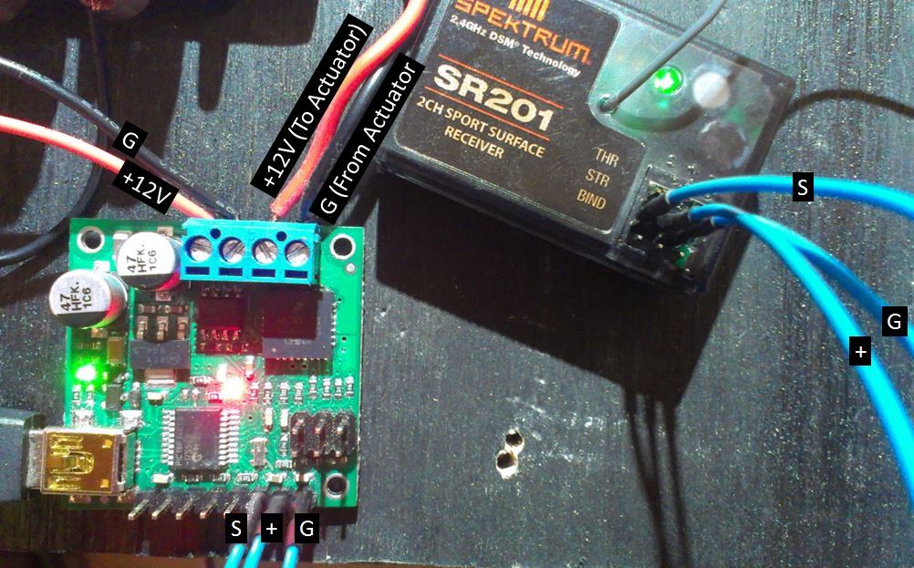
Attached is what I’ve got so far. Did try removing the feedback components but no luck. Maybe a bad receiver or micro-controller?
I inherited this project from a group that had a “bang on it until it works” attitude and didn’t take care of the components very well…
Sadly no oscilloscope but yes, did use a multimeter to get the receiver signal voltages.
Thanks again for all your help!
Electronics_Setup.pdf (568 KB)
Thank you for posting the pictures. It looks like you are powering the receiver from two different sources: a regulator and a wire coming from the jrk’s 5V regulated output pin. Powering something from multiple sources could cause unexpected results or potentially damage something. Could you try removing the regulator and powering the receiver from the jrk’s 5V output? If there was a reason why you wanted to use a separate regulator, could you try removing the wire (labeled “+” in your pictures) that is connected between the receiver and the jrk’s 5V pin instead?
Also, until it is working, could you leave the feedback out of your system and set the feedback mode of the jrk to “none”?
-Brandon
Removed the 5V regulator entirely and using the 5V output from the jrk. Feedback loop connections removed and disabled in the configuration utility. Sadly, still get the invalid input error when set to pulse width, but serial mode still works. 
Thank you for your continued help and patience!!!
B/R
At this point, I suspect that the problem might be from your RC receiver, since your connections look correct and the input invalid error is indicating that the jrk is still not receiving good pulses. Do you have any way to test the receivers output signal (other than a multimeter)? You might be able to hook a servo up to it to see if you can get it to react, although the tolerance of the servo might be less strict than the jrk.
-Brandon
Hi Brandon,
No other measuring devices currently available but had a couple discoveries using a servo.
The receiver works perfectly when hooked up to the spektrum 6V battery pack and a small servo. Knowing this…
Changed the receiver power input to the jrk regulated 5V output and no response. Two differences from operational setup with the servo (besides the reduced voltage):
1) No signal input from the power source (the battery has a signal wire which seems to not serve any purpose with a voltage of 0)
 2) The receiver LED was flashing (assuming a low voltage warning) without the controller powered on.
     (the receiver LED was off until the controller was turned on using the battery pack.  Perhaps the battery signal line is functional.)
Replaced the battery pack and ran the steering signal output to the jrk RX input and the receiver ground to the jrk ground. No luck 
I really don’t want to sacrifice an expensive battery pack for experimental dissection but really curious what’s happening there… the spektrum manuals don’t provide any help.
At the least we know the components aren’t damaged or defective. So pulse width of the receiver may just be incompatible with the jrk?
If the receiver could control your servo, it should be sending compatible pulse widths (assuming the servo works with standard RC pulse widths). The 5V output on the jrk should probably work for powering your receiver for RC control, but it might not be able to provide enough current to power your servo.
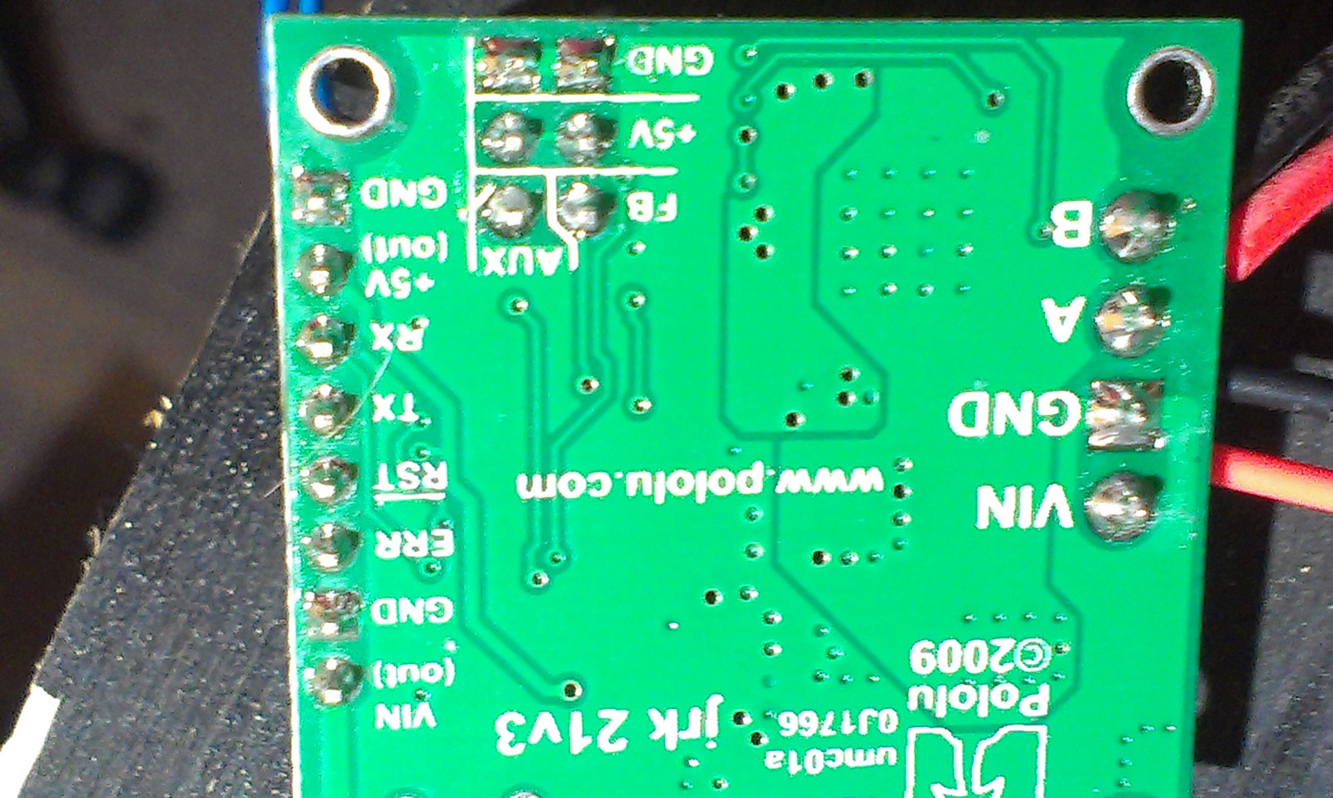
I suspect there might be loose or bad connection. Could you post pictures of the underside of the jrk that show your soldering and connections?
-Brandon
Hey Brandon,
Attached is a picture of the underside of the chip. Thanks again!
Thank you again for posting a picture. All of the soldering looks good to me; I am not sure what is causing the problem. You might try doing a continuity test with your multimeter by probing the receiver’s signal pin with one multimeter lead and the Rx pin on the underside of the jrk with the other. You could quickly test the other connections as well.
If they all seem to be making a connection, then it is possible that the Rx pin might have been damaged in some way. If you are interested in trying again with a new one, you could contact us by email at support@pololu.com, and we can see what we can to do to help you out on a replacement jrk.
-Brandon
Hi Brandon,
The project got tabled over the holidays but, great news, I swapped the chip for one that was still in the factory plastic, applied the settings, and everything works near perfectly! Just some PID tuning and I’m all set. Don’t think I’ll have too much trouble with the PID tuning but I know whom to ask if I do!
Thanks again for all your help, it’s greatly appreciated!
B/R
robo-noob
I am glad that you were able to get everything working how you want it to. Thank you for letting us know. By the way, if you need help with the PID tuning, you might try looking through the information under the “Tuning the PID constants” heading of the “Setting Up Your System” section of the user’s guide.
-Brandon