//This code is for use with the Arduino IDE application to upload to the Arduino board.
//Copy and paste into Arduino IDE and upload to Arduino Uno via USB-A port.
#include <SPI.h>
#include <HighPowerStepperDriver.h>
// Define stepper motor connections and steps per revolution:
//These "pins" are the Arduino electrical connect pins
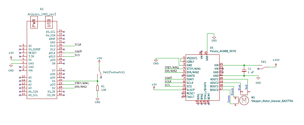
#define dirPin 2
#define stepPin 3
#define buttonPin 4
#define SCPin 10
//These "pins" are solder cup pins on the connector being assembled
#define microSteps 16
#define outerPins 5 //Number of pins on the outer circumfrance of the terminal
#define stepsPerRotation 200 //Number of steps for 1 full rotation of the stepper motor
#define fullStepsPerPin stepsPerRotation/outerPins
#define microStepsPerPin fullStepsPerPin*microSteps
//Set buttonState to 0
int buttonState = 0;
int buttonPrevious = 0;
int offTime = 500;
unsigned long previousTime = 0;
HighPowerStepperDriver sd;
void setup() {
SPI.begin();
sd.setChipSelectPin(SCPin);
// Declare motor pins as output and button pin as input:
pinMode(stepPin, OUTPUT);
pinMode(dirPin, OUTPUT);
pinMode(buttonPin, INPUT);
// Give the driver some time to power up.
delay(1);
// Reset the driver to its default settings and clear latched status
// conditions.
sd.resetSettings();
sd.clearStatus();
// Select auto mixed decay. TI's DRV8711 documentation recommends this mode
// for most applications, and we find that it usually works well.
sd.setDecayMode(HPSDDecayMode::AutoMixed);
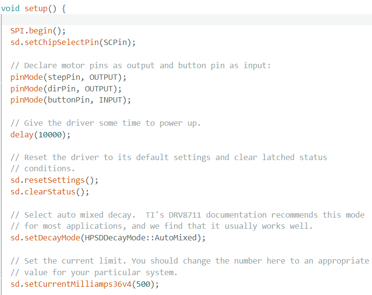
// Set the current limit. You should change the number here to an appropriate
// value for your particular system.
sd.setCurrentMilliamps36v4(500);
// Set the number of microsteps that correspond to one full step.
sd.setStepMode(HPSDStepMode::MicroStep16);
// Enable the motor outputs.
sd.enableDriver();
// Set direction to clockwise
sd.setDirection(0);
}
void loop() {
// Check if button is pressed
buttonState = digitalRead(buttonPin);
unsigned long currentTime = millis();
// Read button press and rotate to next pin location
if (buttonState == HIGH && buttonPrevious == LOW && (currentTime - previousTime) > offTime) {
for (int i = 0; i < microStepsPerPin; i++) {
// These four lines result in 1 step:
sd.step();
delayMicroseconds(1000);
previousTime = currentTime;
}
}
buttonPrevious = digitalRead(buttonPin);
delay(10);
}
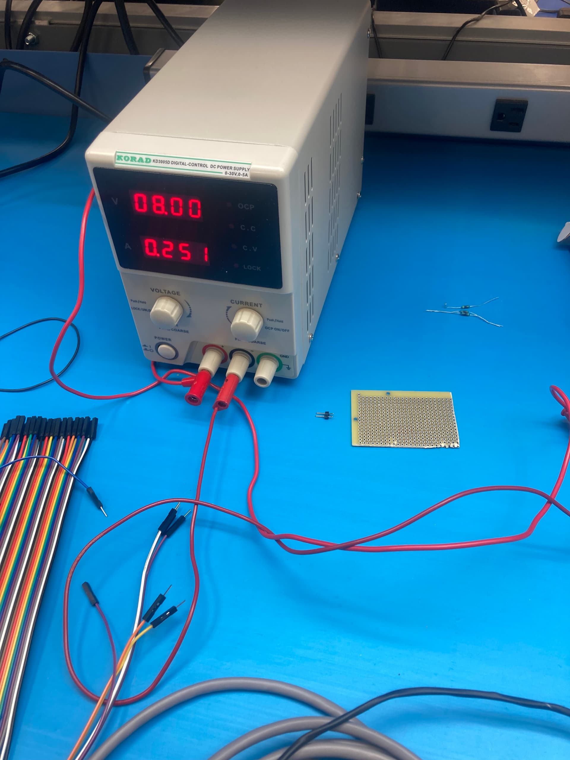
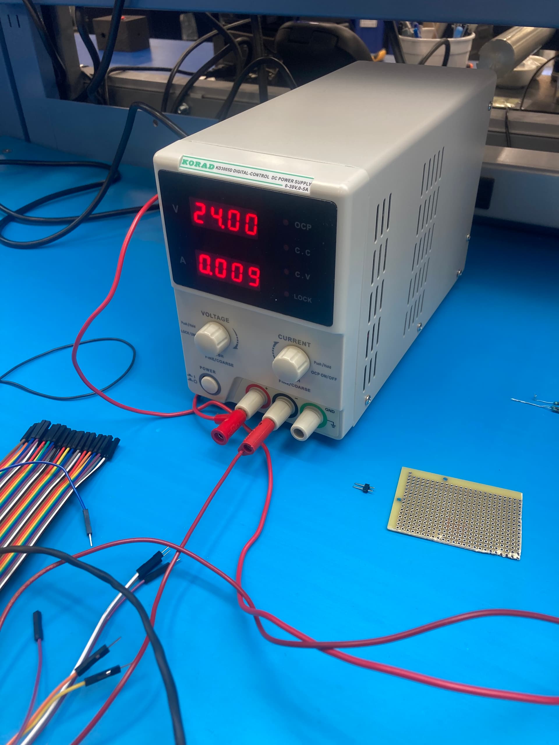
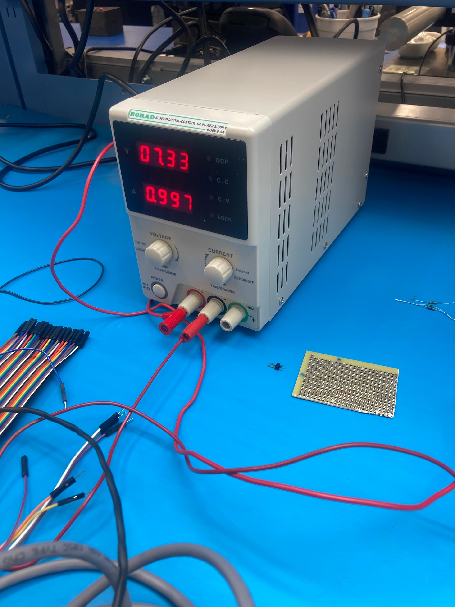
Everything works except for the sd.setCurrentMilliamps36v4(500) is not actually regulating the current. The stepper motor has 5.2 Ohm resistance and we are getting ~7V at 1 amp using a constant current power supply set to 24V 1A. It should be 14V 0.5A, right? The SPI doesn’t seem to be working as intended I think but I don’t know if it’s a setup or a code thing. I tried connecting the SDATO to Pin 12 on the Arduino Uno and still have the same issue. I have this set up in 2 separate formats - 1 is soldered up and one is on a breadboard. Each setup has it’s own driver, motor, and Arduino and both exhibit the same functionality so I think it’s unlikely to be bad components or bad connection, so something in my setup or code must be wrong. Input voltage agrees with the power supply, resistance on the coils is a little higher (a little over 6 Ohms) but basically agrees with the spec. Logic voltage is also reads 5V. If I throw a resistor on the power ground line I can force the current to drop but I’m not a huge fan of this solution as it’s pretty hacky and I’d like to drop the holding current when not in use to avoid the motor heating up (it will be in contact with my hands for extended periods of time for the intended use and don’t want to get cooked).
On a side note, the motor also whines when there is a holding current. Is there any way to get that to go away?
I pulled the sd.setCurrentMilliamps36v4 out of the void setup() and initialized it at the beginning of void loop() and now it’s holding at 24V 0.1A. That being said, using the voltage supply (now running at constant voltage) I have can max out the power supply at 30V, so will I run into an issue with the voltage climbing beyond what the driver is spec’ed at? Really odd that the setCurrent operates differently if defined in setup or loop.
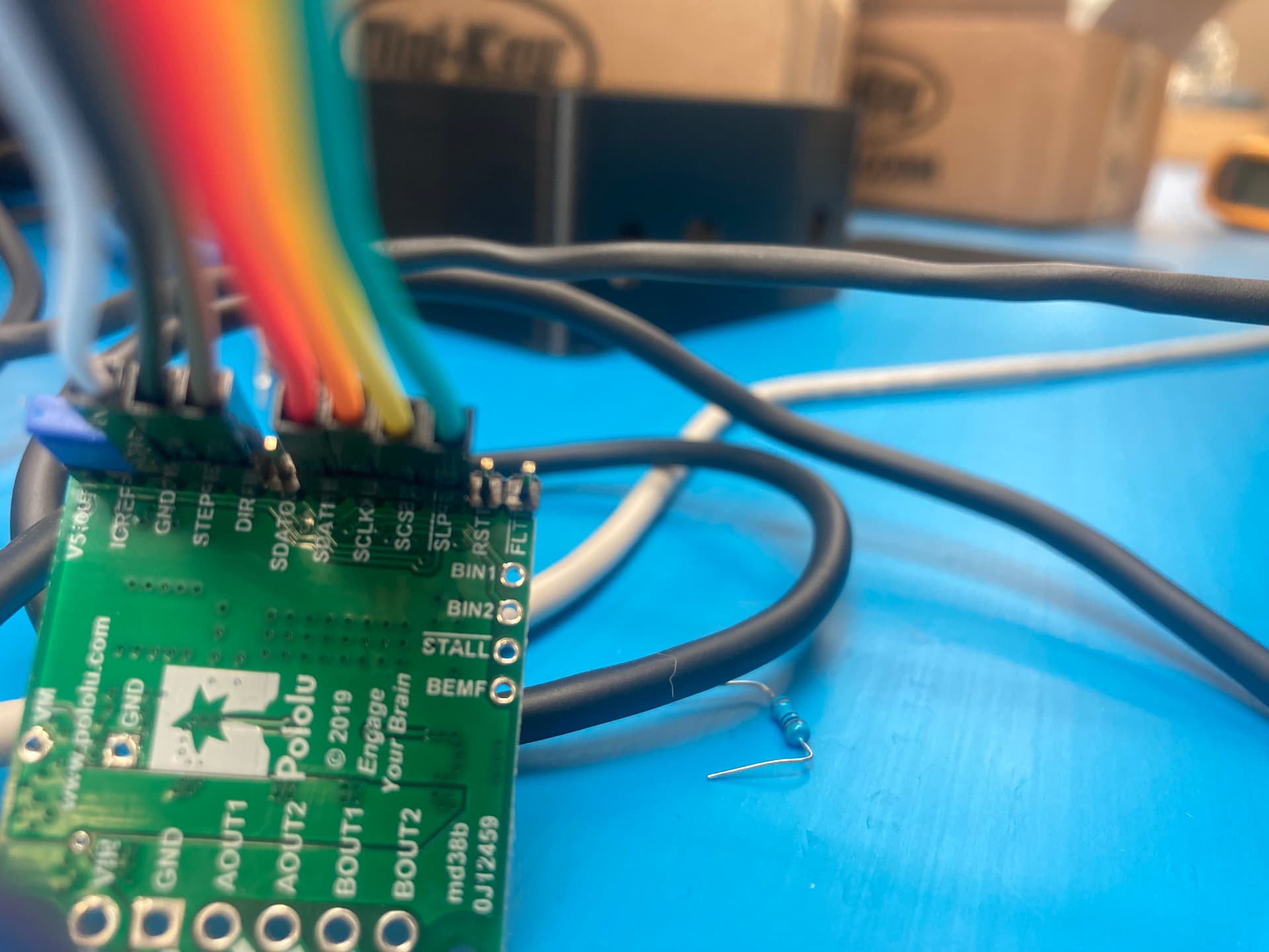
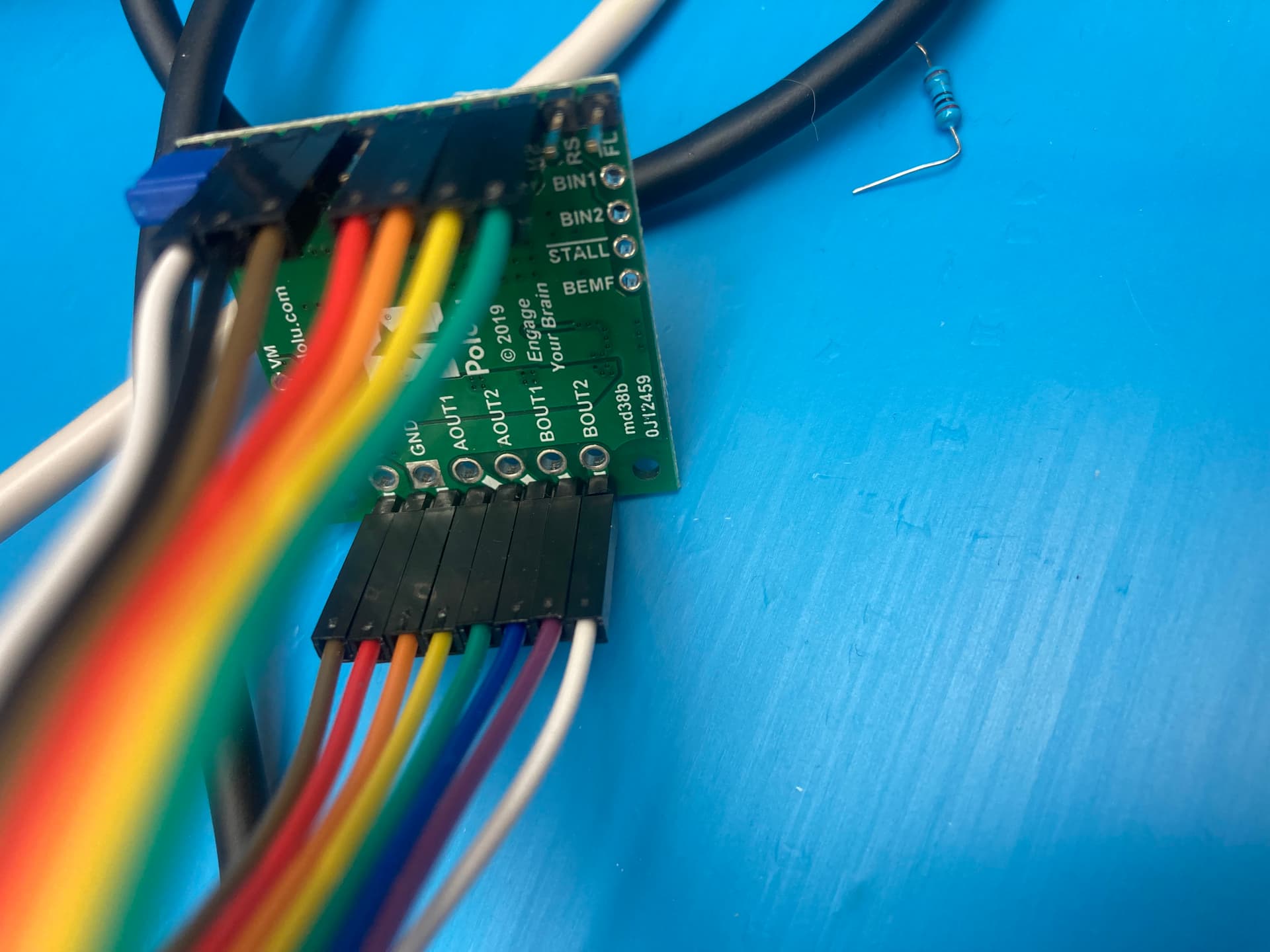
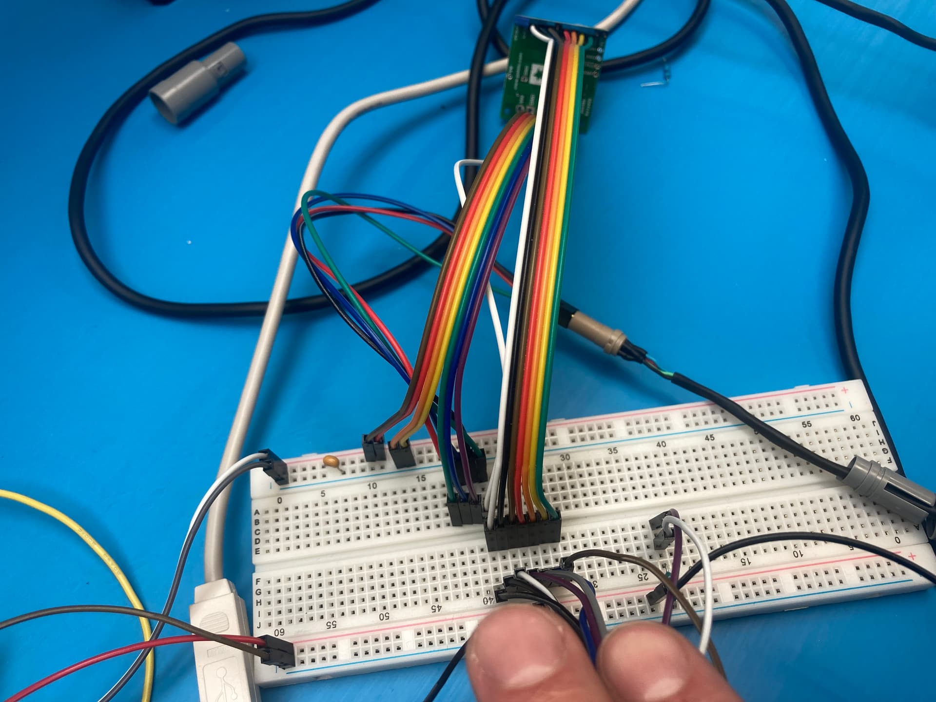
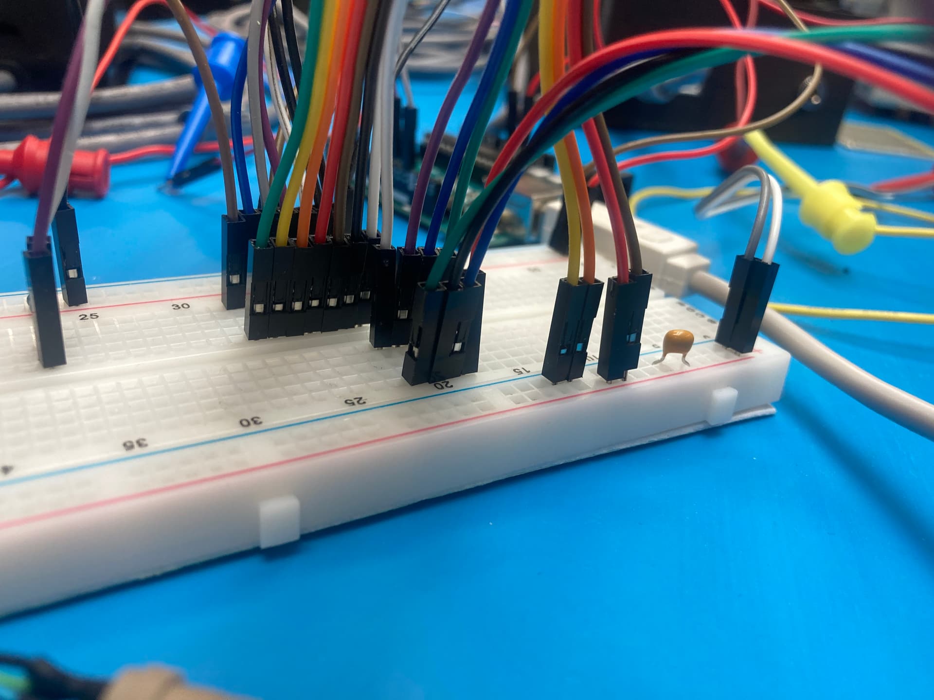
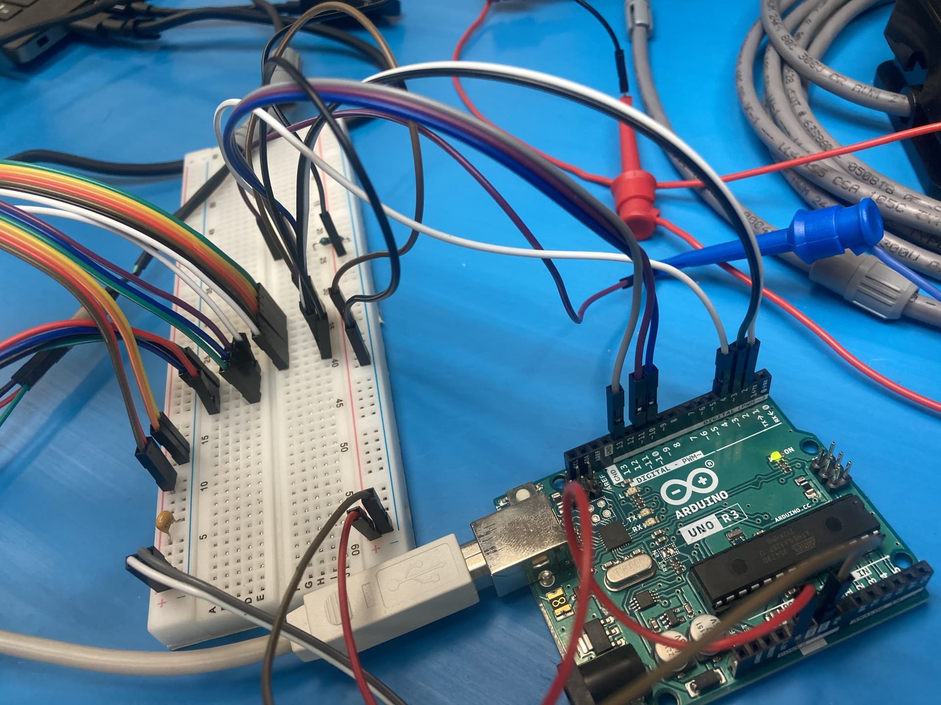
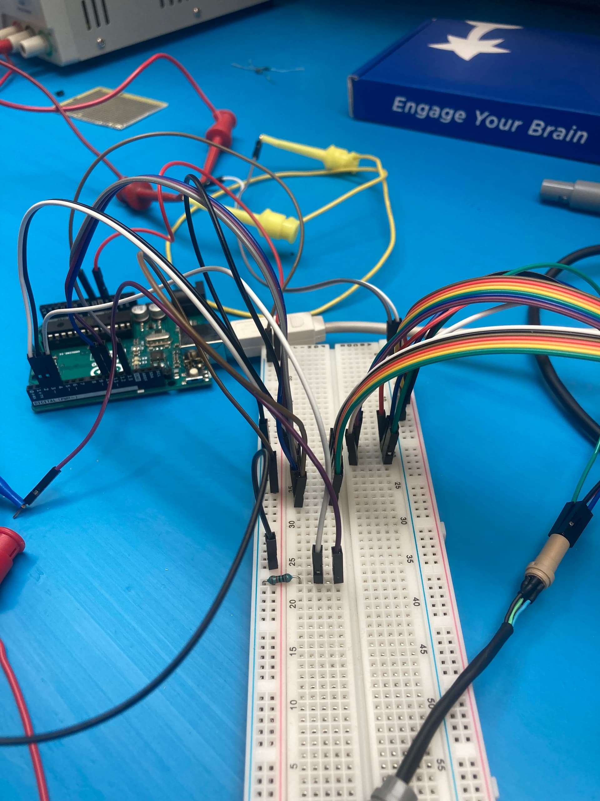
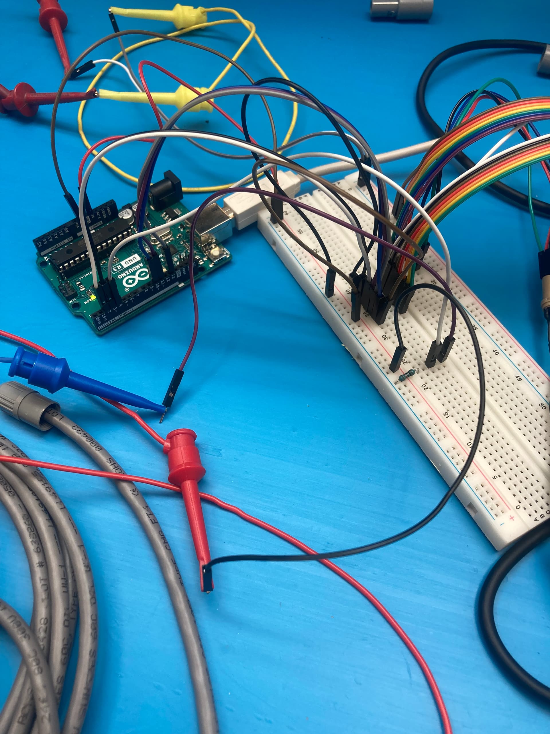
I would suggest putting the setCurrentMilliamps36v4() command back in the setup function for now; you should only need to call it once after the driver is powered up. Could you post some pictures of your physical setup that show all of your connections? It would also be useful to have more details about how you are measuring the current and some pictures showing that.
It is difficult to follow all of your connections, but the most immediate issue is it seems like all of the current measurements you are making are from looking at your adjustable supply, which is not a good way to monitor the current going through the stepper motor coils. Additionally, the voltage value on the supply immediately dropping when you apply power suggests that the supply is limiting the current.
Can you try increasing the current limit on your supply and measuring the actual current through one of the motor coils?
For the power supply current, you can power the system as is and then just increase the limit on the supply until the output holds the at the intended 24V. Then I would turn the dial a little farther past that point to have some safety margin.
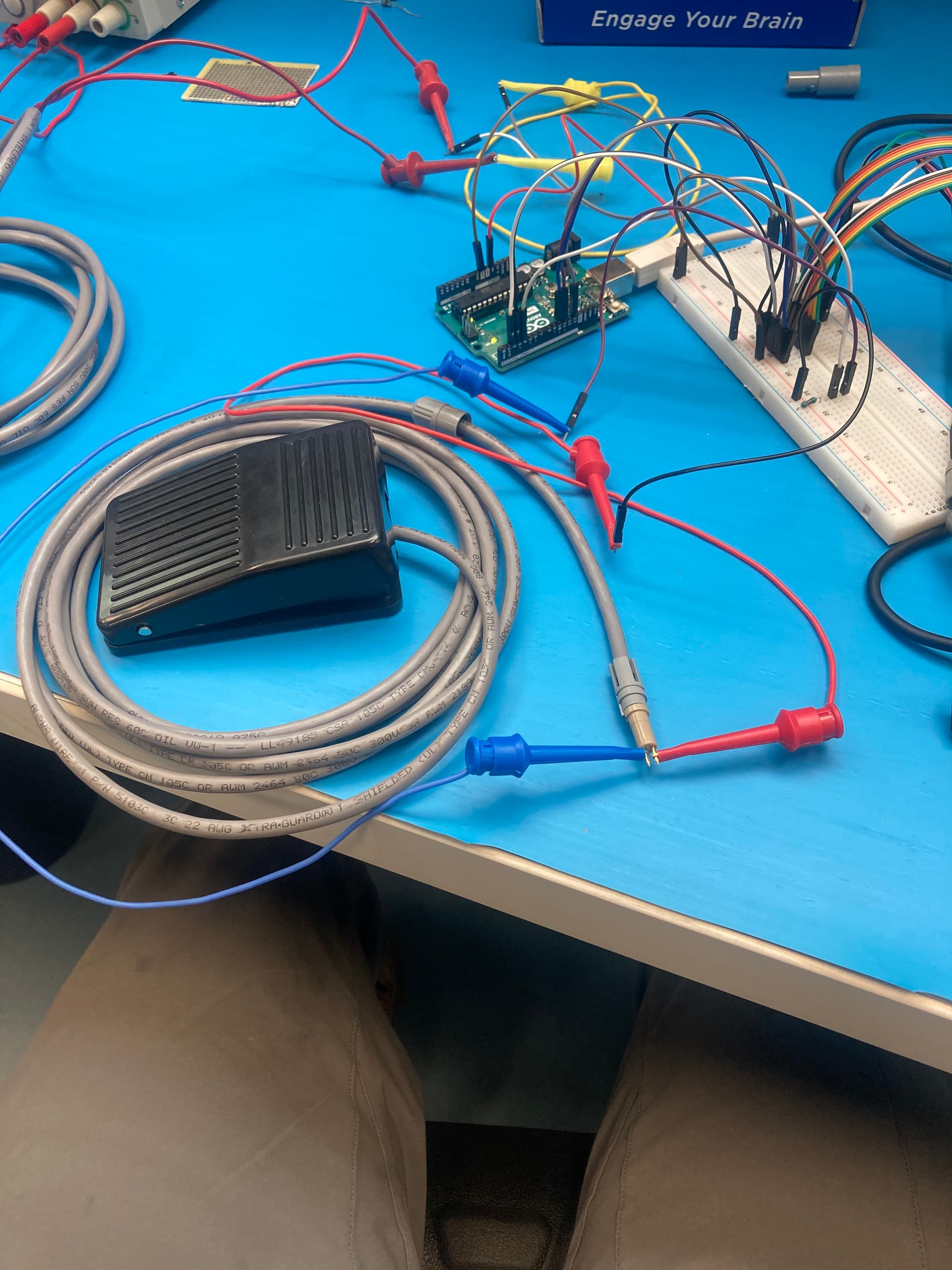
The best way to measure the current through one of the coils would be to upload a program that simply holds the motor stationary at your desired current limit in full step mode, then use a current probe around one of the stepper motor wires for the measurement. However, if you do not have access to a current probe, connecting a multimeter in series with the coil will work as well. Here is a video demonstrates that type of procedure starting around 5 minutes from the beginning. (Please note that this video is mainly about drivers where the current limit is set using a potentiometer, so much of the rest of the video is not applicable to the 36v4.)
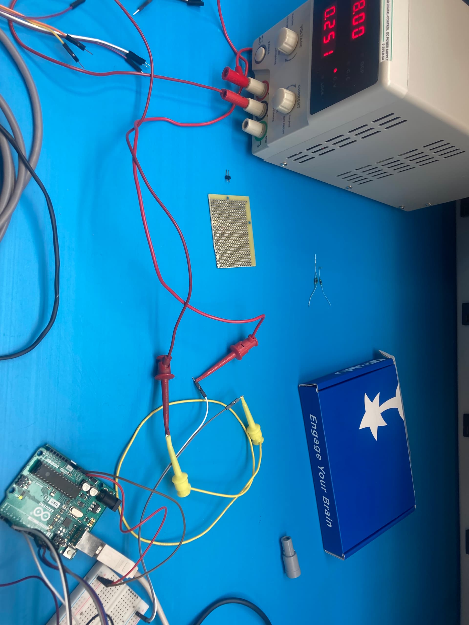
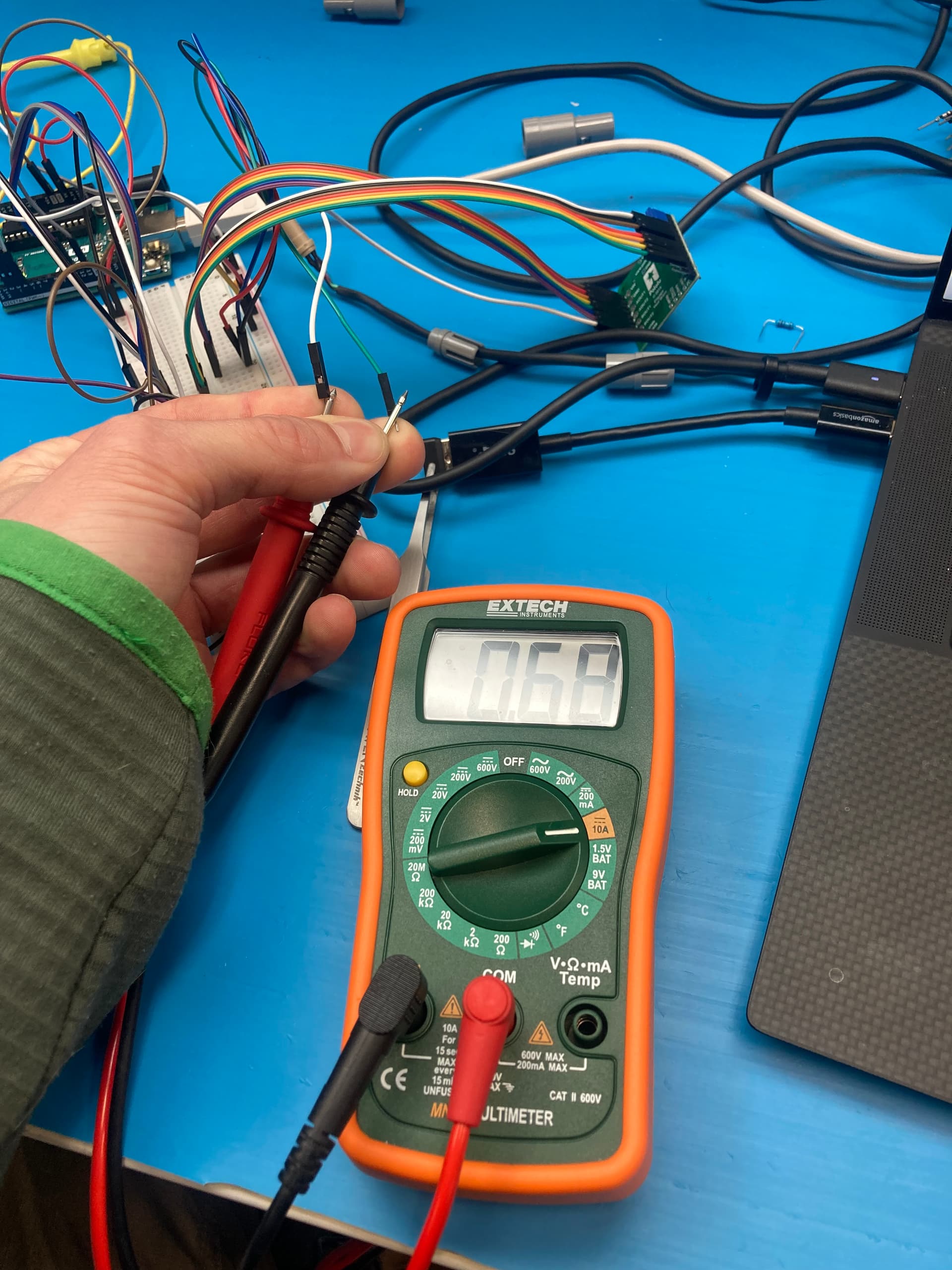
I’m getting 700 mA off the coils when the power supply is set to 1A on a full step hold program. When I bump it up to 1.6A, the coils read 910 mA. Voltage only goes up to 7.8V (7.4V at 1A) so I can’t reach the 24V without risking frying the motor that’s rated to 1A. The power supply is set to 24V but doesn’t reach that because it has a built in current limiter that is set to 1A (before I press the button it’s essentially 0A current so it’s not taking any current before the first button press hence no drop in voltage initially, this is not the case when I swap the location of setCurrent - no idea why this is the case). It’ll take whatever I’m willing to give it. To get 24V the current would be around 4A (V=IR in theory, probably higher on the power supply) which I’m extremely hesitant to go to.
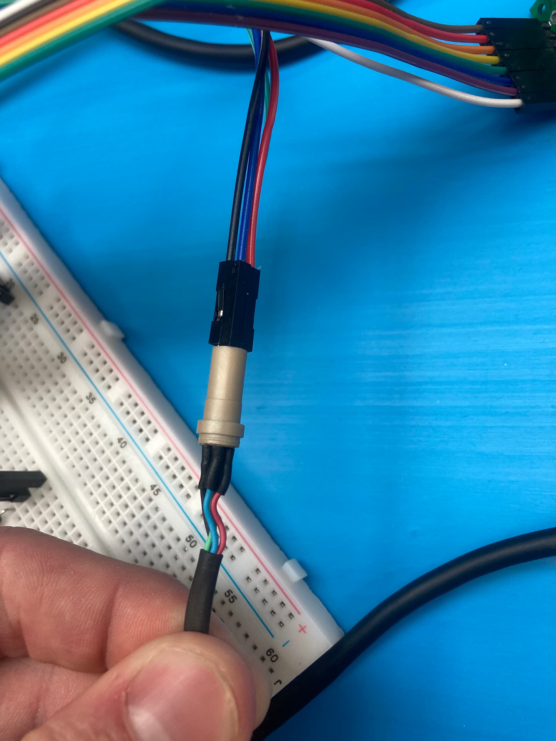
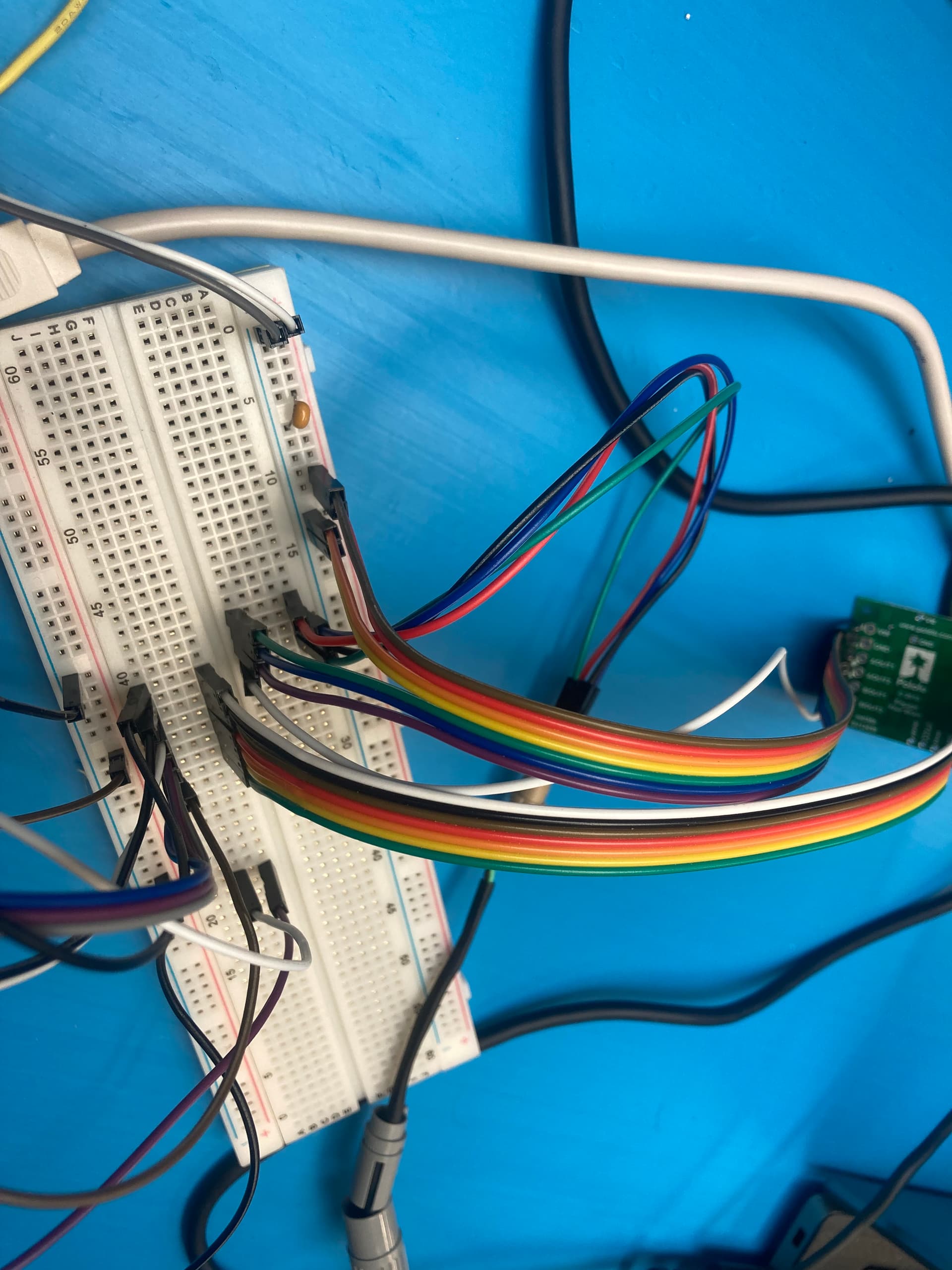
It’s the same program after pressing the button for the hold and I’m testing current using a multimeter in series with one of the coils (initially tested in parallel, hence the edit on the last comment). The white line is coming from the board and the green line is going to the motor.
I did some testing and it has to be something with the button not being pressed before the current gets set. If I leave the setCurrent in setup() but set the delay for powering up the driver to 10000ms and press the button before that delay ends then it works fine, but if I don’t press the button in those 10000ms then it still has the same issue. This doesn’t work if I hold the button while I turn the power on. By “works” I mean running at 24V (setpoint) and 0.1A (set at 1A so voltage limited) without the annoying whining noise.
I checked the current in this “working” configuration and it is 400mA at the coil while measuring in series. In this configuration it is holding at the current limit set by the driver in the setup().
Just to confirm, is the button you are referring to the one connected to your Ardunio, labeled as SW2(Footswitch) in your initial post? Can you verify that everything about the driver work as expected if you disconnect that switch and remove any of the code for it? An easy way to test that would be to use one of the example programs from our 36v4 stepper motor driver library with minimal modification.
By the way, since you mentioned initially trying to measure current with your multimeter connected in parallel, definitely try to avoid making that mistake in the future. Connecting your meter like that while it is in a current measuring mode essentially creates a short circuit between the points you are probing and could damage your electronics.
I didn’t know that! This is my first electronics project and am learning a lot through this process. Yes, by button I’m referring to the footswitch (SW2). I ran the code below and it worked but still was running at 700 mA at the coil (fluctuating but was not limited by setCurrent) even with the footswitch disconnected. I put the same 10000ms delay in line 28 (after pinMode and digitalWrite) and if I push the footswitch within that time then it runs correctly (setCurrent limited by the driver). So does this mean it’s something with the setup/hardware since the footswitch isn’t being called in by the code at all? Edit: I tried testing it with the 10s delay without pressing the footswitch, and it works, but if I cycle power, it immediately goes back to the “bad” case (not current limited) and doesn’t delay for 10s. If I reset the Arduino and run it again then it works in the current limited case. This appears to work all the way down to the 1ms delay, but I have to reset the Arduino every time. I didn’t realize order mattered when uploading new code and resetting the Arduino. I tried again with the original code and this functions the same way working with the 1ms delay, but needs to be reset when power is cycled.
Edit: I’m thoroughly confused now. I came back a few hours later and tried resetting the Arduino but it’s jumping to the “bad” case straight away with either the original code or the test code… I didn’t change anything and I’m performing the reset when I cycle power the same as I was this morning. It’s not until I reach a 1000ms delay that it goes to the “good” current limited case after turning off, resetting the Arduino, and turning back on power to the driver.
Edit: If I power on the driver before I plug the Arduino in, it works every time without resetting the Arduino (is unplugging the Arduino a “reset”?). When I power on the driver first, the power supply reads a small current output for an instant (17 mA) then drops to 0mA.
// Before using this example, be sure to change the setCurrentMilliamps36v4 line
// to have an appropriate current limit for your system.  Also, see this
// library's documentation for information about how to connect the driver:
//   http://pololu.github.io/high-power-stepper-driver
#include <SPI.h>
#include <HighPowerStepperDriver.h>
const uint8_t CSPin = 10;
const uint8_t StepPin = 3;
const uint8_t DirPin = 2;
// This period is the length of the delay between steps, which controls the
// stepper motor's speed.  You can increase the delay to make the stepper motor
// go slower.  If you decrease the delay, the stepper motor will go faster, but
// there is a limit to how fast it can go before it starts missing steps.
const uint16_t StepPeriodUs = 2000;
HighPowerStepperDriver sd;
void setup()
{
  SPI.begin();
  sd.setChipSelectPin(CSPin);

  // Drive the STEP and DIR pins low initially.
  pinMode(StepPin, OUTPUT);
  digitalWrite(StepPin, LOW);
  pinMode(DirPin, OUTPUT);
  digitalWrite(DirPin, LOW);

  // Give the driver some time to power up.
  delay(1); //This is where I'm putting in the 10000ms delay

  // Reset the driver to its default settings and clear latched status
  // conditions.
  sd.resetSettings();
  sd.clearStatus();
  // Select auto mixed decay.  TI's DRV8711 documentation recommends this mode
  // for most applications, and we find that it usually works well.
  sd.setDecayMode(HPSDDecayMode::AutoMixed);
  // Set the current limit. You should change the number here to an appropriate
  // value for your particular system.
  sd.setCurrentMilliamps36v4(500);
  // Set the number of microsteps that correspond to one full step.
  sd.setStepMode(HPSDStepMode::MicroStep32);
  // Enable the motor outputs.
  sd.enableDriver();
}
void loop()
{
  // Step in the default direction 1000 times.
  sd.setDirection(0);
  for(unsigned int x = 0; x < 1000; x++)
  {
    sd.step();
    delayMicroseconds(StepPeriodUs);
  }
  // Wait for 300 ms.
  delay(300);
  // Step in the other direction 1000 times.
  sd.setDirection(1);
  for(unsigned int x = 0; x < 1000; x++)
  {
    sd.step();
    delayMicroseconds(StepPeriodUs);
  }
  // Wait for 300 ms.
  delay(300);
}
Let’s focus on getting the simplest possible system working first, so we should disregard the footswitch for now (leave it disconnected).
It seems like you might be running into some kind of power issue. Is your benchtop power supply maintaining 24V during these tests; and can you try to confirm that with something other than the supply’s display? The ideal tool for that would be an oscilloscope if you have access to one (you mentioned being new to electronics, but maybe a friend has one that you can borrow). How is your Arduino being powered during these tests, and if you power it separately from the driver (e.g. via USB), does that change any of your results?
Also, can you try adding this function I wrote to your program (you can add it after the loop() function):
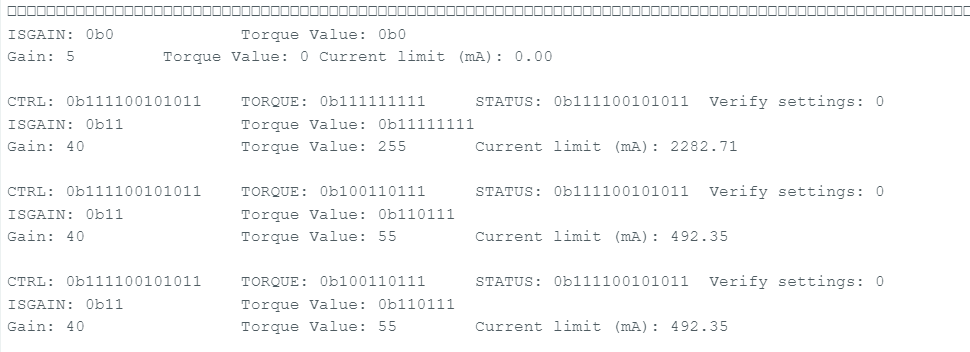
From the debug code I get the following as an output. Code attached for reference to make sure I have it set up correctly. I added Serial.begin(9600); in the setup() to get the serial monitor to work.
// Before using this example, be sure to change the setCurrentMilliamps36v4 line
// to have an appropriate current limit for your system. Also, see this
// library's documentation for information about how to connect the driver:
// http://pololu.github.io/high-power-stepper-driver
#include <SPI.h>
#include <HighPowerStepperDriver.h>
const uint8_t CSPin = 10;
const uint8_t StepPin = 3;
const uint8_t DirPin = 2;
// This period is the length of the delay between steps, which controls the
// stepper motor's speed. You can increase the delay to make the stepper motor
// go slower. If you decrease the delay, the stepper motor will go faster, but
// there is a limit to how fast it can go before it starts missing steps.
const uint16_t StepPeriodUs = 2000;
HighPowerStepperDriver sd;
void setup()
{
Serial.begin(9600);
SPI.begin();
sd.setChipSelectPin(CSPin);
// Drive the STEP and DIR pins low initially.
pinMode(StepPin, OUTPUT);
digitalWrite(StepPin, LOW);
pinMode(DirPin, OUTPUT);
digitalWrite(DirPin, LOW);
// Give the driver some time to power up.
delay(1);
// Reset the driver to its default settings and clear latched status
// conditions.
sd.resetSettings();
sd.clearStatus();
// Select auto mixed decay. TI's DRV8711 documentation recommends this mode
// for most applications, and we find that it usually works well.
sd.setDecayMode(HPSDDecayMode::AutoMixed);
// Set the current limit. You should change the number here to an appropriate
// value for your particular system.
sd.setCurrentMilliamps36v4(500);
// Set the number of microsteps that correspond to one full step.
sd.setStepMode(HPSDStepMode::MicroStep32);
// Enable the motor outputs.
sd.enableDriver();
debug();
}
void loop()
{
// Step in the default direction 1000 times.
sd.setDirection(0);
for(unsigned int x = 0; x < 1000; x++)
{
sd.step();
delayMicroseconds(StepPeriodUs);
}
// Wait for 300 ms.
delay(300);
// Step in the other direction 1000 times.
sd.setDirection(1);
for(unsigned int x = 0; x < 1000; x++)
{
sd.step();
delayMicroseconds(StepPeriodUs);
}
// Wait for 300 ms.
delay(300);
debug();
}
void debug(){
  uint16_t ctrlReg = sd.driver.readReg(HPSDRegAddr::CTRL);
  uint16_t torqueReg = sd.driver.readReg(HPSDRegAddr::TORQUE);
  uint16_t statusReg = sd.driver.readReg(HPSDRegAddr::CTRL);

  Serial.print("CTRL: 0b");
  Serial.print(ctrlReg, BIN);
  Serial.print("\tTORQUE: 0b");
  Serial.print(torqueReg, BIN);
  Serial.print("\tSTATUS: 0b");
  Serial.print(statusReg, BIN);
  Serial.print("\tVerify settings: ");
  Serial.println(sd.verifySettings());

  uint8_t ISGAIN = ctrlReg >> 8 & 0b11;
  uint8_t torqueVal = torqueReg & 0b11111111;

  Serial.print("ISGAIN: 0b");
  Serial.print(ISGAIN, BIN);
  Serial.print("\t\tTorque Value: 0b");
  Serial.println(torqueVal, BIN);

  uint8_t gain = 0;
  switch (ISGAIN){
    case 0:
      gain = 5;
      break;
    case 1:
      gain = 10;
      break;
    case 2:
      gain = 20;
      break;
    case 3:
      gain = 40;
      break;
  }

  float currentLimit = 1000*2.75*torqueVal / (256*gain*0.030);

  Serial.print("Gain: ");
  Serial.print(gain);
  Serial.print("\t\tTorque Value: ");
  Serial.print(torqueVal);
  Serial.print("\tCurrent limit (mA): ");
  Serial.println(currentLimit);

  Serial.println();
}
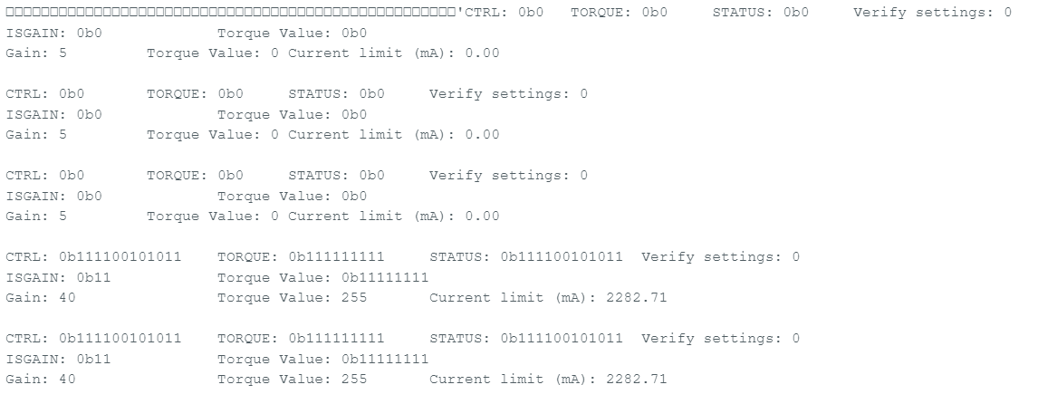
I will need to see if I can get my hands on an oscilloscope but using the multimeter it is holding 7V and the power supply is at 7.3V. If I do one of the hacks I’ve mentioned previously (in this case moving setCurrent into the loop) to get it to run in the setCurrent limited state then it holds 24V on the multimeter. The outputs in the “hacky” state to get it to appear to work are below:
I apologize, in my previous reply I forgot to mention that you would probably need to add Serial.begin(9600); to the setup() function.
At this point you have tested your driver in several different configurations. Can you tell me exactly what the differences are in what you are currently describing as the “hacky” state?
For the “hacky” state described in my last post I am
Moving the setCurrentMilliamps36v4() out of setup() and putting it at the beginning of loop().
A few other “hacky” states I’ve gotten it to “work” without moving setCurrentMilliamps36v4() out of setup() are:
2. Powering on the driver before I power on the Arduino. This seems to give the driver some time to get into whatever state it needs to properly set the current. The power supply when first powered on (before the Arduino is plugged in) shows a small current output (~17mA) before dropping to 0mA until the Arduino is powered on.
3. Resetting the Arduino before turning on the power supply. This seems to intermittently work at a delay(1) in the setup() for the driver to power on but only reliably seems to work at delay(1000) or more, though I have played with the delay so much I’m not 100% sure what I’ve tried isolating the delay() as a cause. Currently it works at delay(1). When I cycle power on the power supply using this method, it goes back to the non-current limited state if I don’t reset the Arduino again.
I have not checked the outputs on Serial Monitor for 2 or 3 above, just 1 which I posted previously. Also, I forgot to answer one of your earlier questions. I am powering the Arduino through the USB port currently.
We have clear evidence now from the serial output that some of the driver’s registers (including the ones related to the current limit) are not saving the same values that you are sending. One way that could happen is if the driver is not powered when your Arduino program starts running, so it is very important to make sure that the driver is always powered whenever you power up, reset, or upload a new program to the Arduino. Does the current limit always set correctly if you use the driver that way? Does that cause any other issues with your setup?
Have a single 24V in, 24V to the driver and a split to a 5V regulator that goes to the Arduino power jack
Have a delay (1000ms seemed to be plenty, but more wouldn’t be the end of the world) at the beginning of the setup() to allow the driver to power up fully
Currently the Arduino is powered separately through USB, and in the configuration I have will ultimately stay powered on basically indefinitely so will never go back into setup() until unplugged and rebooted.