i have a qik 2s9v1 and an trying to use it to drive 2 dc motors on a sumobot. I have got to it to work by shorting a and b together but when i go to upload code i get this message "avrdude: stk500v2_ReceiveMessage(): timeout "
i am using a arduino mega 2560 if it helps and i tried to upload the example code for it and some i found on other fourms. hope someone can help see what is going on
update
i am working on it now and just found out that i am only getting the error when i plug the pins from the qik into the arduino when i unplug the pins it uploads but doesnt do anything. so does that mean I have something wrong with my code??
Try reseting the arduino and disconect it from your computer, if that doesent work you can turn off and on your computer or restart the arduino program
i do not what the error pin hooked up because i am not sure where to put it
and from the qik to the motors i have the leads hooked up, and the positive and negative of the battery are connected to the vmot and gnd on the qik.
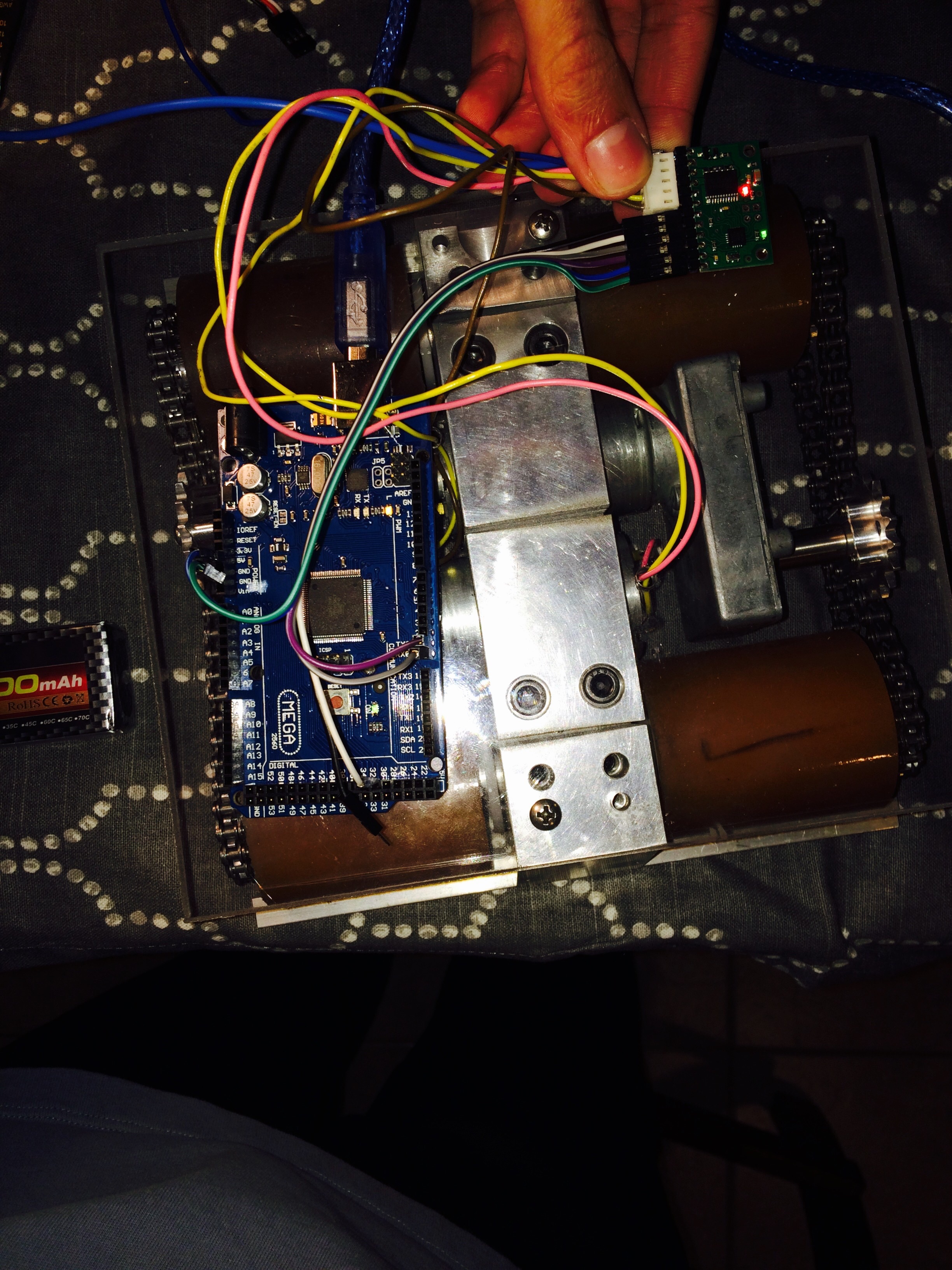
it is all for a 3kg sumobot. the deadline to get it totally done is in the middle of january so I’m really trying to get it done as fast as i can so any help/code would be appreciated. and let me know if anyone wants the picture sorry about that it says the pic is invalid.
Thanks for the photo. Unfortunately, your finger covers up half the connections to the qik. Could you post another photo that clearly shows all the connections as well as close-up photos of both sides of the qik? If you had problems uploading the photo, I suspect it was because the file was too large. You might try reducing its size before trying to upload it. Alternatively, you might try taking the pictures at a lower resolution.
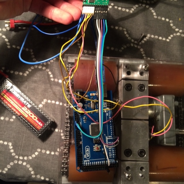
if i did it right there should be the 2 different blocks of code i tried and the new picture.
/*
Optionally writes, then reads, the configuration parameters on the qik 2s9v1.

Please note that the memory used to store these parameters is only rated
for approximately 100,000 erase/write cycles, so you should avoid
repeatedly setting configuration parameters. It is intended that these
parameters will initially be configured as desired and then only changed
occasionally (they are saved in non-volatile memory, which means that
once set, these parameters will retain their values even if the unit is
powered off). For example, you can uncomment the appropriate calls to
setConfigShowResult() below and run this program once to initialize the
parameters. Then, you can load your final program on your Arduino, which
should assume that the parameters have already been set correctly.

Required connections between Arduino and qik 2s9v1:

      Arduino   qik 2s9v1
-------------------------
           5V - VCC
          GND - GND
Digital Pin 2 - TX
Digital Pin 3 - RX
Digital Pin 4 - RESET
*/

#include <SoftwareSerial.h>
#include <PololuQik.h>

char* param_names[] = {
  "Device ID",
  "PWM Parameter",
  "Shut Down Motors on Error",
  "Serial Timeout"
};

PololuQik2s9v1 qik(1, 0, 30);

void setConfigShowResult(uint8_t parameter, uint8_t value)
{
  Serial.print("Setting ");
  Serial.print(param_names[parameter]);
  Serial.print(" to ");
  Serial.print(value);

  byte result = qik.setConfigurationParameter(parameter, value);

  switch (result)
  {
    case 0:
      Serial.println(": Command OK");
      break;

    case 1:
      Serial.println(": Bad parameter");
      break;

    case 2:
      Serial.println(": Bad value");
      break;
  }
}


void setup()
{
  Serial.begin(115200);
  Serial.println("qik 2s9v1 dual serial motor controller");
  Serial.println();

  qik.init();

  // Write configuration parameters
  // Uncomment and edit the line for any parameter you want to change.

  //setConfigShowResult(QIK_CONFIG_DEVICE_ID, 9);
  //setConfigShowResult(QIK_CONFIG_PWM_PARAMETER, 0);
  //setConfigShowResult(QIK_CONFIG_SHUT_DOWN_MOTORS_ON_ERROR, 1);
  //setConfigShowResult(QIK_CONFIG_SERIAL_TIMEOUT, 0);

  Serial.println();

  // Read configuration parameters

  for (int i = QIK_CONFIG_DEVICE_ID; i <= QIK_CONFIG_SERIAL_TIMEOUT; i++)
  {
    Serial.print(param_names[i]);
    Serial.print(": ");
    Serial.println(qik.getConfigurationParameter(i));
  }
}

void loop()
{
  // do nothing
}
/*
Required connections between Arduino and qik 2s12v10:

      Arduino   qik 2s12v10
---------------------------
          GND - GND
Digital Pin 2 - TX
Digital Pin 3 - RX
Digital Pin 4 - RESET

DO NOT connect the 5V output on the Arduino to the 5V output on the qik 2s12v10!
*/

#include <SoftwareSerial.h>
#include <PololuQik.h>

PololuQik2s12v10 qik(1, 0, 30);

void setup()
{
  Serial.begin(115200);
  Serial.println("qik 2s12v10 dual serial motor controller");

  qik.init();

  Serial.print("Firmware version: ");
  Serial.write(qik.getFirmwareVersion());
  Serial.println();
}

void loop()
{
  for (int i = 0; i <= 127; i++)
  {
    qik.setM0Speed(i);
    if (abs(i) % 64 == 32)
    {
      Serial.print("M0 current: ");
      Serial.println(qik.getM0CurrentMilliamps());
    }
    delay(5);
  }

  for (int i = 127; i >= -127; i--)
  {
    qik.setM0Speed(i);
    if (abs(i) % 64 == 32)
    {
      Serial.print("M0 current: ");
      Serial.println(qik.getM0CurrentMilliamps());
    }
    delay(5);
  }

  for (int i = -127; i <= 0; i++)
  {
    qik.setM0Speed(i);
    if (abs(i) % 64 == 32)
    {
      Serial.print("M0 current: ");
      Serial.println(qik.getM0CurrentMilliamps());
    }
    delay(5);
  }

  for (int i = 0; i <= 127; i++)
  {
    qik.setM1Speed(i);
    if (abs(i) % 64 == 32)
    {
      Serial.print("M1 current: ");
      Serial.println(qik.getM1CurrentMilliamps());
    }
    delay(5);
  }

  for (int i = 127; i >= -127; i--)
  {
    qik.setM1Speed(i);
    if (abs(i) % 64 == 32)
    {
      Serial.print("M1 current: ");
      Serial.println(qik.getM1CurrentMilliamps());
    }
    delay(5);
  }

  for (int i = -127; i <= 0; i++)
  {
    qik.setM1Speed(i);
    if (abs(i) % 64 == 32)
    {
      Serial.print("M1 current: ");
      Serial.println(qik.getM1CurrentMilliamps());
    }
    delay(5);
  }
}
Our Arduino qik library uses the Arduino SoftwareSerial library. This does not allow you to use hardware serial pins for communication. Since you are using an Arduino Mega, only certain pins support the change interrupts used by the library. As stated in the SoftwareSerial Library, you can only use the following pins for RX on the Mega: 10, 11, 12, 13, 50, 51, 52, 53, 62, 63, 64, 65, 66, 67, 68, 69. Could you try changing the communications pins to use those pins (e.g. you can declare the constructor as PololuQik2s9v1 qik(10, 11, 30)
If you still have problems programming the Arduino after moving the communication pins, could you remove the motor connections from the qik and then try programming the Arduino?
ok i did what you said and i have good news and bad news. the good news is it uploaded fine and had no errors. the bad news is that it didn’t do anything, the rx and tx lights flashed on the arduino and the aref light is still on. I’m not sure it that is good or not. and i also tried (50,51,30) and it did not change. and also there’s the green heartbeat on the qik so im guessing there is no problems there. now we just need to find why the code isnt doing anything. and i opened the serial monitor and it displayed this " qik 2s9v1 dual serial motor controller Firmware version: " so im guessing the code did something but it just didn’t get to the loop. We are one step closer
never mind i got it working i had the tx and rx pins backwards thanks a lot for all the help, now i just need to make code to make it run like a sumobot. thanks a lot
i just have one 2 more questions for you where does the error pin go on the arduino, i was just curious in case i need it later on in the coding. and on my robot i have one of the motors turned backwards so right now i have 2 wheels going forward and 2 going backwards what is the best way to get the 2 wheels to go forward since the qik has reverse polarity protection.
i was just looking at the #2511 specs and i saw that it can handle 1.2 amps continuous and 1.5 max my motors draw 1.5 amps under full load so will this work with my motors. that draw could be for up to a minute, so would it overheat or turn off at that load for so long. just trying to keep my options open and not get the wrong one.
The error pin on the qik drives high when an error occurs and is pulled low normally, so you can connect it to any IO pin on your Arduino to read the pin. You can read more about the error pin in the “Logic Connections” section of the qik 2s9v1 user’s guide.
You should be able to compensate for the direction of the motor in your code or by flipping the connections on the motor driver output pins on the qik. The reverse polarity protection has nothing to do with the way the motors spin; it protects the components on the board if power is connected backwards.
With the DRV8835 shield, you will be close to its operating limit if your motors draw 1.5A. I recommend using a motor driver shield that handle more current, like our dual MC33926 motor driver shield.
I got my new shield today, I got it all sodered together and it works great . I got it to go straight and turn but cannot get it to go backwards. I put a negative value in and it either just turned one wheel backwards or just skipped over that part of the program I’m not sure what im doing wrong hope someone can help thanks
It is not clear from your post which shield you got. If you have the MC33926 dual motor driver shield, did you try running the demo example found in the Dual MC33926 Motor Driver Shield Arduino library? If the demo does not turn the motor in both directions, could you remove your motors from the shield and try powering them directly by connecting power with one polarity then the other to drive them in both directions?
Yes I got the mc 33926 motor shield, in the demo the one motor only goes forward I tried switching the leads and switching the motors so it isn’t the specific motor or power trouble here’s a pic of my setup
Over the phone, you said that you were able to get one channel to work properly, but you were only able to drive the motor in one direction on the other channel. This makes me suspect you have a connection issue with the DIR pin for that channel. Could you measure the voltage on the M1DIR and M2DIR pins I point to in the image I attached to this post, first with the motors programmed to drive forward and then with the motors programmed to drive in reverse? If the channel that is not working behaves different than the working channel, you probably have a bad connection, and you should check your soldering. If you post closeup pictures of your soldering I could also take a look at it.
ok, it did what you said and when i programed both motors to go foward i have no power on m1dir or m2dir and when i put it in reverse i have no power on m1dir and 5 volts on m2dir. and i checked all of my soldering and redid some of it, so that is not the issue. im not sure if the chip for m1 could be damaged from the begining or what another problem could be.