Hello there,
I need some help with calibrating my 8 array sensors with my arduino 2560 micro-controller. I am a beginner when it comes to programming, so I picked this sensor because of the extensive library it has with arduino. as it turns out the calibrating program provided is not written for the mega 2560 but previous models. I worked on some code to try to get some reading from the sensors and I did but the values are just jumping which tells me the calibration is completely wrong. Can someone help me calibrate these sensors? here is the code I am using to get the values:
int s1, s2, s3, s4, s5, s6, s7, s8;

void loop() {

  pinMode(42, OUTPUT);     //set sensor pins as digital pins and as output
  digitalWrite(42, HIGH);  //write a 1 to each sensor
  delayMicroseconds(10);  // delay for 10 us
  pinMode(42, INPUT);      //set digital pins as input to read sensors
  delay(2);
  s1 = digitalRead(42);

  pinMode(44, OUTPUT);
  digitalWrite(44, HIGH);
  delayMicroseconds(10);  // delay for 10 us
  pinMode(44, INPUT);
  delay(2);
  s2 = digitalRead(44);

  pinMode(46, OUTPUT);
  digitalWrite(46, HIGH);
  delayMicroseconds(10);  // delay for 10 us
  pinMode(46, INPUT);
  delay(2);
  s3 = digitalRead(46);

  pinMode(48, OUTPUT);
  digitalWrite(48, HIGH);
  delayMicroseconds(10);  // delay for 10 us
  pinMode(48, INPUT);
  delay(2);
  s4 = digitalRead(48);

  pinMode(50, OUTPUT);
  digitalWrite(50, HIGH);
  delayMicroseconds(10);  // delay for 10 us
  pinMode(50, INPUT);
  delay(2);
  s5 = digitalRead(50);

  pinMode(52, OUTPUT);
  digitalWrite(52, HIGH);
  delayMicroseconds(10);  // delay for 10 us
  pinMode(52, INPUT);
  delay(2);               //wait 2ms before reading
  s6 = digitalRead(52);

  pinMode(51, OUTPUT);
  digitalWrite(51, HIGH);
  delayMicroseconds(10);  // delay for 10 us
  pinMode(51, INPUT);
  delay(2);               //wait 2ms before reading
  s7 = digitalRead(51);

  pinMode(53, OUTPUT);
  digitalWrite(53, HIGH);
  delayMicroseconds(10);  // delay for 10 us
  pinMode(53, INPUT);
  delay(2);               //wait 2ms before reading
  s8 = digitalRead(53);
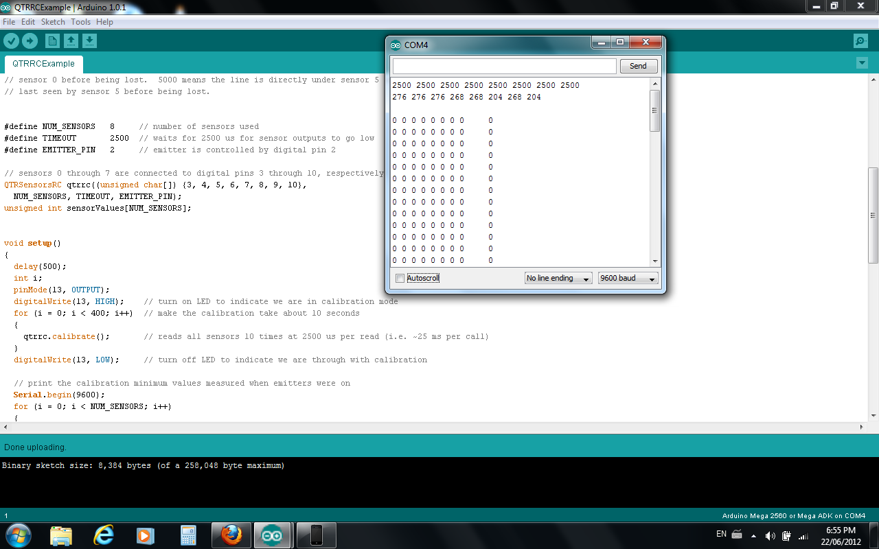
I just tested it here and verified that our Arduino Library for the Pololu QTR Reflectance Sensors works on an Arduino Mega 2560. I recommend using our library and the example sketch that it comes with (QTRRCExample) as a starting point. Please try running QTRRCExample and looking at its output in the serial monitor. Be sure to set the baud rate to 9600 in the serial monitor. If it doesn’t work, please copy and paste the output from the serial monitor so we can see it, and give us more information: How have you connected the QTR-8RC to your Arduino and how is everything powered? What did you do during the first 10 seconds of that sketch to calibrate the sensors? A picture of your setup showing how everything is connected would help too.
The example code you posted will not work well because you are leaving the AVR’s internal pull-up enabled, which will fight against the pull-down in the sensor and probably prevent the line from ever going low. Also, it will only ever give you one bit of information for each sensor.
hello david,
I connected each sensor output to pins 3 to 10 from the arduino mega and took the ground from one of the six front ground outputs and connected it. the vcc i took from the pin in front of output sensor two. I gave the circuit 5v from the power supply in the lab. I uploaded the exact example file and for the calibration I first place a white sheet of paper about 3mm on top and then moved it and placed a black sheet of paper on it. the results I got is attached in a file and the connections are also attached in a file to this massage.
It looks like you did not connect the Arduino Mega’s GND to the GND of the QTR-8RC sensor. Please do that and see if it fixes the problem. In general, all the grounds in your system should be connected unless you are doing something very special.
I will try that as soon I get to the lab. I thought I could use just one of the ground pins on the sensor. I will try this and let you know how it works out as soon I get it.
I am a beginner, and I want to interface the QTR-8RC sensors with the arduino 2560 mega.
it is the first time that I am using an arduino board and the sensors, too.
I have downloaded the QTR sensors library then I tried to upload the example to try to calibrate it.
The example was uploading with no errors, but no results are coming on the screen. Also, the LED’s of the sensors are not coming ON ( All LED’s are OFF).
The connections I have made :
I connect the 8 sensors to the digital pins 3-10 respectively.
I connect the LEDON to the digital pin 2.
I connect the Vcc to a +ve pole of a 6V battery.
I connect the GND (that close to the Vcc) to the -ve pole of the battery.
I connect the GND ( that below the sesnors) to the GND pin on the power section of the arduino board.
Please I want to Know what are the correct steps that I have to follow, and I want you to check my connections.
On the QTR-8RC product page, we list the operating voltage as 3.3 - 5.0 V, so it is not good to connect the sensor to your 6V battery. Please connect the sensor’s VCC to your Arduino’s 5V pin or to some other regulated 5V supply.
To see results on your screen, you will need to launch the Arduino’s Serial Monitor, which can be found in the Tools menu. Make sure its baud rate is set to 9600.
As a general reminder, be sure to solder the header pins into the sensor.
If you continue to have trouble, providing more information will help us troubleshoot this. Where did you download the library from? Please provide a link to the page where you found it. What is the exact name of the example you are running? What baud rate is your serial monitor set to? What version of the Arduino IDE do you have? Did you see any warning messages when compiling? What procedure do you follow to calibrate the sensors when the Arduino first starts up? Also, if you are seeing numbers on the screen but they look wrong, please provide some pictures showing all of your connections.
I would like to inform you that, I got results the varying for 0 to 9 whenever I move my figers in front of the sesnors.
After that, I restarted the program to double check that I am on the safe side, but the results become zeros the the time.
Hello. It is hard to evaluate the soldering from those pictures. Could you post a picture of the other side of the sensor so I can see the solder joints?
Are you powering the sensor from the Arduino’s 5V pin now, as I suggested? Again, what is the exact name of the example you are running? Again, what procedure do you follow to calibrate the sensors when the Arduino starts up? This last question seems especially important to investigate because you said that the data from the program got worse after you restarted the Arduino. Every time you restart the Arduino you must follow a calibration procedure that exposes the sensors to all the different light levels that you want to distinguish.
Thanks for the additional pictures. To understand the calibration, please read all the comments at the top of QTRRCExample. To make things easy, here is a copy of the second paragraph, with emphasis added by me:
When the Arduino starts up, you will see the yellow LED light up for 10 seconds. During this time you need to calibrate the sensors by exposing them to the lightest and darkest readings they will encounter. The numbers at the top of your last picture are all 2500, which means something went wrong during the calibration.
I got the proper results and I understand how to calibrate it, but I have one more problem with the LEDs. I am not getting the LEDs ON. What is your note on this problem?? and what is the differences if the LEDs are ON or OFF? What is the benefits to make the LEDs ON ?
Hello. Please note that the LEDs on the QTR-8RC are infrared, so you cannot simply look at it with your eyes and tell whether they are on or not. How did you determine that the LEDs are off? The example code you are using is supposed to turn on the LEDs when taking readings.
I think it is better to have the LEDs on for the same reason that you have lights in your house: the light should let your sensors see a better contrast between different surfaces and it should be much more reliable than depending on ambient IR, which might be shining at a bad angle or have some shadows.

