Zumo with Quadrature Encoders

It would be really great if the Zumo (pololu.com/catalog/product/1217.
I understand that the reflectance is a problem, and I might hack around it. But a ‘clean’ encoder solution would be great.

Or any other good way to add encoders to the micro metal-gear motors.
I saw that you have some with ‘extended’ shaft, so that might be an option?

Thanks for consideration,
Erich

Hello.

We do not have any encoders that work with that chassis at this time. However, the versions of our micro metal gearmotors with extended shafts do fit inside the Zumo, so you could try to make some kind of custom encoder for those motors yourself.

- Grant

To reopen this thread, do the new encoders for the micrometal gearmotors fit into the space provided on the Zumo? I notice there is some buttressing near the center of the motor compartment. If they do fit, would you recommend using the 100:1 extended shaft HP motors?

Thanks, Jim

Hello, Jim.

Our new micro metal gearmotor encoders do fit inside the Zumo chassis. However, you would probably need to use a custom mounting plate or drill a hole in the chassis to get access to the encoder leads.

- Grant

I just installed the encoders on my Zumo. I have a few pics here : wp.me/p493sy-aI

The modification to the chassis was simple enough. Getting the encoders on to the motors was a challenge for me. I used hot glue to position it for soldering. I also cut off a small section of the first spacer above where the encoders are located. It seemed I was getting some minor contact between the encoder wheel and the casing while I was testing the assembly, so giving it a little extra room can’t hurt.

My only two nit-picks with the Zumo Shield is that the motor driver is not on I2C like the compass. I’d love to have those four pins freed up for devices and sensors. I also wish the shield provided comparators for converting the encoders. I understand it raises the cost but I think would make the the bot a great little platform for general bot development.

Hello.

Thanks for sharing your modifications with us in such details. We do not have comparators on the shield because the shield was made before we had those encoders. In the future we might consider adding comparators to future electronics for the Zumo chassis. For now, you might try using the Arduino I/O lines directly as comparators, before trying to preprocess the encoder signal.

In regards to making the motor driver use an I2C interface, this is something that would require a separate microcontroller and firmware, raising the complexity of the shield significantly.

The modifications are really cool and we plan to make a blog post of them in the community projects section of our blog. We’d love to hear more about your project and see video of it once you get it running.

- Grant

Thanks for the feedback, Grant. Much appreciated. I’m certainly having fun with it all.

I’ll give this a shot. Just got an oscilloscope and logic analyzer so I’m not going to be so in the dark as before.

For sure. I actually have an Adafruit Trinket I think I could use to control the motors if I need to free up pins on the main board.

I’ll certainly keep you guys posted if I get anything useful working. Just wish I had more free time… It’s a lot of fun. :slight_smile:

Just a quick update to let you know that I got the encoders working, without any comparators. Just connected them directly to the Arduino.

Worked like a charm. Very strong clean signals from the sensors:

Got max peaks of 4V and 3.25V for each signal (same for both encoders).

Can’t get over the resolution of these guys; 1200 ticks per wheel turn. Just crazy. Had to up the signal sampling frequency to 16Khz and that’s not even fast enough to cover the top speeds of the motors.

Very impressed with how well they are working. Totally worth the effort.

Unfortunately sampling at 16KHz seems to be be too high a frequency for the 16MHz processor.

While the encoder side of things works fine, the excessive CPU load means that other systems, like the Servo lib and pulseIn(), are impacted. In plain English: the bot’s servo is jittery and the sonic sensor returns garbage readings…

Not sure what the solution is. Whatever it is, It’s not trivial. Maybe add a circuit to “divide down” the encoder resolution to something manageable. That actually might be an interesting sub project. I need to do some pure electronics stuff anyway.

How are you reading the encoder signals? Could you post a simplified version of the code that still demonstrates the problem?

- Grant

I’ve written about the encoder code here: solderspot.wordpress.com/2014/01 … r-wallbot/

Basically it’s a high frequency interrupt routine that samples the inputs and updates a tick counter.

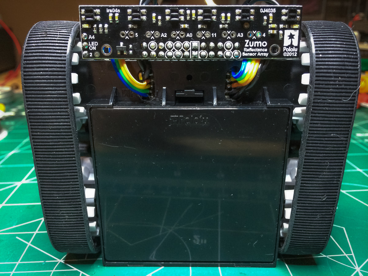
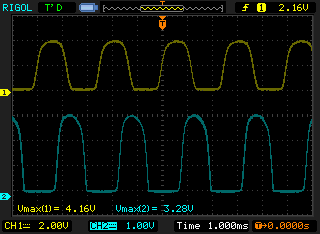
For the Zumo bot I’m also using the interrupt to drive the motor PWM signals. Here is the code:

/ Copyright (c) 2014, Solder Spot
// All rights reserved. 
// See license.txt 

#if USE_ENCODERS
#define TICK_HZ   16000L
#define CYCLE_HZ  250L
#define CYCLE_TICKS (TICK_HZ/CYCLE_HZ)

//----------------------------------------
//
//----------------------------------------

// encoder data
volatile int16_t en_lft_ticks = 0;
volatile int16_t en_rht_ticks = 0;
volatile uint16_t en_counter = 0;
volatile bool en_error = false;
char en_lApin;
char en_lBpin;
char en_rApin;
char en_rBpin;

// motor data
// each tick is 62.5 usec
// 64 ticks per cycle
struct MotorData
{
     char   on_ticks;
     volatile bool      on;
     volatile char   ticks_left;
     char     pin;
};

MotorData x_motor[2];
void init_motor( MotorData *m, char pin );
void update_motor( MotorData *m );

//----------------------------------------
//
//----------------------------------------

void setup_encoder( char lftPinA, char lftPinB, char rhtPinA, char rhtPinB )
{
  en_init_pin( &en_lApin, lftPinA);
  en_init_pin( &en_lBpin, lftPinB);
  en_init_pin( &en_rApin, rhtPinA);
  en_init_pin( &en_rBpin, rhtPinB);

  init_motor( &x_motor[LEFT], 10 );
  init_motor( &x_motor[RIGHT], 9 );
    
  cli();
  // set timer2 interrupt at 16000 Hz
  // we are assuming a clk speed of 16MHz
  TCCR2A = 0;
  TCCR2B = 0;
  TCNT2  = 0;
  OCR2A = 124;
  TCCR2A |= (1 << WGM21);
  TCCR2B |= (1 << CS21);   
  TIMSK2 |= (1 << OCIE2A);
  sei();
}

//----------------------------------------
//
//----------------------------------------

void en_init_pin( char *pin, char value)
{
  *pin = value;
  pinMode(value, INPUT);
  digitalWrite( value, LOW);
}

//----------------------------------------
//
//----------------------------------------

bool get_ticks_since_last( int16_t *lft, int16_t *rht, uint16_t *ms )
{
  cli();
  *lft = en_lft_ticks;
  *rht = en_rht_ticks;
  *ms = en_counter>>4;
  en_lft_ticks = en_rht_ticks = en_counter = 0;
  char error = en_error;
  en_error = false;
  sei();

  return !error;
}

//----------------------------------------
//
//----------------------------------------

void clear_ticks()
{
  cli();
  en_lft_ticks = en_rht_ticks = en_counter = 0;
  en_error = false;
  sei();
}

//----------------------------------------
//
//----------------------------------------

ISR(TIMER2_COMPA_vect)
{
  en_counter++;

  static char lastLA = 0;
  static char lastLB = 0;
  static char lastRA = 0;
  static char lastRB = 0;

  en_process(en_lApin, en_lBpin, &lastLA, &lastLB, &en_lft_ticks);
  en_process(en_rApin, en_rBpin, &lastRA, &lastRB, &en_rht_ticks);
  update_motor( &x_motor[LEFT] );
  update_motor( &x_motor[RIGHT] );
}

//----------------------------------------
//
//----------------------------------------

void en_process( char Apin, char Bpin, char *lastA, char *lastB, volatile int16_t *ticks )
{
  char A = (digitalRead( Apin) == HIGH) ? 1 : 0;
  char B = (digitalRead( Bpin) == HIGH) ? 1 : 0;
  char lA = *lastA;
  char lB = *lastB;
  char dA = A!=lA;
  char dB = B!=lB;

  if( dA && dB )
  {
    // both should not change at the same time
    en_error = true;
  }
  else if ( dA || dB )
  {
    if (A^lB) 
    {
      *ticks += 1;
    }
    else if(B^lA)
    {
      *ticks -= 1;
    }
  }
  *lastA = A; 
  *lastB = B;
}

void init_motor( MotorData *m, char pin )
{
  m->on_ticks = 0;
  m->on = false;
  m->ticks_left = CYCLE_TICKS;
  m->pin = pin;
}

void set_motor( int index, char level )
{
  x_motor[index].on_ticks = level;
}

void update_motor( MotorData *m )
{
  if ( --(m->ticks_left) < 0 )
  {
    if ( m->on )
    {
        // turn off?
         m->on = !(m->ticks_left =  CYCLE_TICKS - m->on_ticks);
        if( !m->on )
        {
          digitalWrite( m->pin, LOW );
        }
    }
    else
    {
        // turn on?
        m->on = (m->ticks_left =  m->on_ticks) != 0;
        if( m->on )
        {
          digitalWrite( m->pin, HIGH );
        }
    }
  }
}

Once I go above 1KHz then servo and sensor functions get messed up as I assume their timings get thrown off.

I’m actually solutioning this by offloading the sensor and servo logic to another microcontroller, an ATtiny85, and controlling it through the I2C bus. Still debugging it all but getting close to being complete. I’ll post about the final build when it’s done.

Thanks for the followup.

Hello, solderspot.

Thank you for sharing all of the great things you are doing with the Zumo robot! Offloading the encoder processing to another microcontroller would definitely help, but I think you should be able to get it all working decently on one MCU if you make your code more efficient. For example, I suggest you detect encoder transitions with a pin-change interrupt rather than a high-frequency timer interrupt. This means interrupts occur only as much as necessary. Also, you are doing a lot in your timer interrupt when your goal should be to make the ISR as short and quick as possible (to minimize the load on the processor and the disruption to other interrupts). One easy improvement would be to move the code that updates the motors out of the ISR and into your main loop. Another would be to remove function calls from the ISR since jumping to a function and returning is relatively slow. Have you taken a look at our library code for reading quadrature encoders?

- Ben

That is true. I should try the pin interrupts for better efficiency. In my original bot I couldn’t as it needed SoftwareSerial for the PololuQik motor controller to work.

For a side project I’ll try to get it all working under one MCU as I’m curious about what the Arduino Uno can handle.

Got it working with the pin interrupts. It was very easy to set up. Didn’t use your encoder libs, just modified the existing code. I did use the Timer2 servo code given in the Zumo manual and it works great too.

The sonic sensor and the servo work fine with the new setup - no jitters or bad readings. Maybe if the bot goes at full speed there might be some issues but I’ve no intention of maxing out the motors or the encoders.

Can still do more optimizations. A big one is giving each encoder it’s own interrupt. That would halve the amount of processing per interrupt. Can also read the pin ports directly.

Had forgotten about the pin interrupts. Thanks for reminding me. Going to see if it is possible to use an interrupt for the sensor’s echo pin. That would remove a significant blocking call that’s resulting in jerky servo moments, and would keep the readings accurate.

Still glad I did the second processor route, even if it wasn’t necessary. Means I can free up 3 of the Arduino’s pins if needed.

That’s great; I’m glad you got it working both ways!

- Ben

Seeing as I posted some code earlier, for completeness sake I though I should post the final version that uses pin interrupts.

Note that the code is hard-coded for pins 2, 3, 4 and 5 on the ATmega328. You are better off using Pololu’s encoder library but if you were to use this code then you’d have to figure out the proper pin mappings for your microcontroller.


volatile int16_t en_lft_ticks = 0;
volatile int16_t en_rht_ticks = 0;
volatile bool en_error = false;
long en_lastCall = 0;
 
// hard coding the pins to port D  
char en_rApin = 2;
char en_rBpin = 3;
char en_lApin = 4;
char en_lBpin = 5; 

//----------------------------------------
//
//----------------------------------------

void setup_encoder()
{
  cli();
      PCMSK2 = ((1<<PCINT21)|(1<<PCINT20)|(1<<PCINT19)|(1<<PCINT18));
      PCICR = (1<<PCIE2);
      PCIFR = 0xFF;
  sei();
}

//----------------------------------------
//
//----------------------------------------

bool get_ticks_since_last( int16_t *lft, int16_t *rht, uint16_t *ms )
{
  cli();
  *lft = en_lft_ticks;
  *rht = en_rht_ticks;
  long now = millis();
  *ms = (uint16_t)(now - en_lastCall);
  en_lastCall = now;
  en_lft_ticks = en_rht_ticks = 0;
  char error = en_error;
  en_error = false;
  sei();

  return !error;
}

//----------------------------------------
//
//----------------------------------------

void clear_ticks()
{
  cli();
  en_lft_ticks = en_rht_ticks = 0;
  en_error = false;
  en_lastCall = millis();
  sei();
}

//----------------------------------------
//
//----------------------------------------

ISR(PCINT2_vect)
{

  static char lastLA = 0;
  static char lastLB = 0;
  static char lastRA = 0;
  static char lastRB = 0;

  en_process(en_lApin, en_lBpin, &lastLA, &lastLB, &en_lft_ticks);
  en_process(en_rApin, en_rBpin, &lastRA, &lastRB, &en_rht_ticks);
}

//----------------------------------------
//
//----------------------------------------

void en_process( char Apin, char Bpin, char *lastA, char *lastB, volatile int16_t *ticks )
{
  char A = (digitalRead( Apin) == HIGH) ? 1 : 0;
  char B = (digitalRead( Bpin) == HIGH) ? 1 : 0;
  char lA = *lastA;
  char lB = *lastB;
  char dA = A!=lA;
  char dB = B!=lB;

  if( dA && dB )
  {
    // both should not change at the same time
    en_error = true;
  }
  else if ( dA || dB )
  {
    if (A^lB) 
    {
      *ticks += 1;
    }
    else if(B^lA)
    {
      *ticks -= 1;
    }
  }
  *lastA = A; 
  *lastB = B;
}

As a follow-up to this thread and about signal processing of the encoder signal, have a look at Optical Motor Shaft Encoder in Zumo with Signal Processing, there is as well a link to the Eagle files of that processing PCB.

We took that approach further and have created our own Zumo board with ARM processor on it and Arduino shield headers. The board includes the comparator circuit and works very well:
Details: https://forum.pololu.com/t/modding-the-zumo-encoders-wifi-gps-usb-and-120-mhz/7286/1

Erich