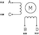
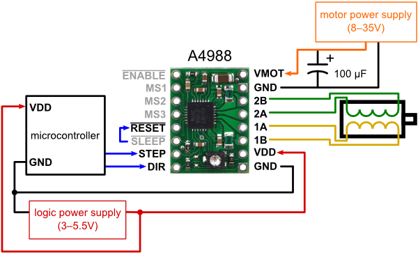
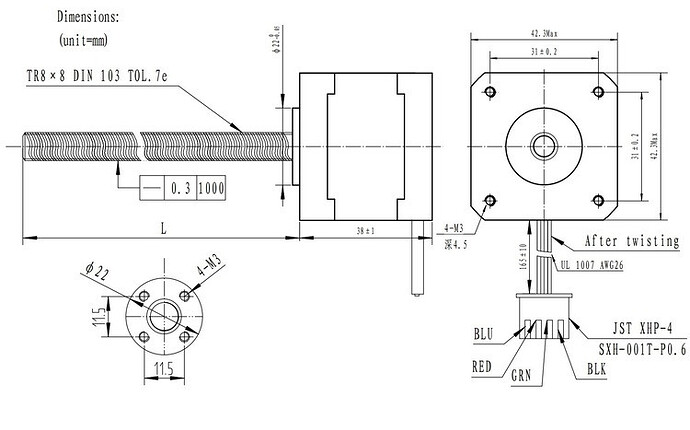
When connecting the item# 1182 stepper motor to a A4988 Stepper Motor Driver Carrier the driver board order is 2B-2A-1A-1B. According to the FAQ, leads B & D are 2A & 2B, while A & C are 1A & 1B. This would result in a color order of Blu-Red-Blk-Grn down the right side of the carrier.
The motor however is wired Blu-Red-Grn-Blk. According to the instructions, this will make the motor run backwards. This would be true in full step mode, but would result in the coils being energized in the wrong order when microstepping. Should I swap the pins on the motor lead, or is this actually done for a reason?

Item #2268 wiring diagram The above diagram shows a standard bipolar stepper motor. To control this with the A4988, connect stepper leads A and C to board outputs 1A and 1B, respectively, and stepper leads B and D to board outputs 2A and 2B, respectively. Note that if you happen to swap which way the wires are connected for any coil, the stepper motor will turn in the opposite direction, and if you happen to pair up wires from different coils, the motor should be noticeably erratic when you try to step it, if it even moves at all. See the A4988 datasheet for more information.
Stepper Motor with 28cm Lead Screw: Bipolar, 200 Steps/Rev, 42×38mm, 2.8V, 1.7 A/Phase


