Hi everybody, I’d like to know which is the best choice talking about the Wild Thumper Robot 6 Wheels. I’d like to control each wheel independently. If anyone knows, just let know which one.
Thanks a lot. ![]()
Hi everybody, I’d like to know which is the best choice talking about the Wild Thumper Robot 6 Wheels. I’d like to control each wheel independently. If anyone knows, just let know which one.
Thanks a lot. ![]()
Hello,
I’m not sure what you mean by the “best” choice. The 6WD Wild Thumpers are available in 34:1 and 75:1 gear ratios, and there is a speed vs. torque trade-off between the two, so you need to consider your intended application to make a choice. Specifications for both versions are listed in the product descriptions for the Wild Thumpers.
Note that all of the motors on each side of the chassis are wired together in parallel by default, but if you really wanted to control each wheel independently, you could separate out the individual connections.
- Kevin
Thanks Kevin, and what about the speed controller???
Hello,
Sorry, I did not realize that you were asking about motor controller choices. However, you never mentioned controllers in your initial post! Please read the product page for the Wild Thumper chassis (pololu.com/catalog/product/1560). There are a number of recommendations for controllers that you can use with it in the “Using the Chassis” section, and you can choose one based on which features are important to you.
Since our motor and robot controllers all have only one or two channels, you would need at least 3 motor controllers (for 6 channels) to be able to control each motor independently. However, if you left the motors on each side wired in parallel, you could control them with only two channels; just make sure the controller can handle the current requirements of all three motors on each side.
- Kevin
I have just completed my adapted version of this and I used two of the Pololu Simple Motor Controllers, was simple to hookup and all is working fine. I would caution against tring to control the motors independently as the amount of tourque stess on these little motors would eat them up in no time, especialy at speeds.
Thanks for the feedback! I’m glad to hear that it was easy to get things working with two paired Simple Motor Controllers. What controller version did you end up using? Like you, I definitely recommend keeping the motors on each side connected in parallel rather than trying to control all six motors independently.
- Ben
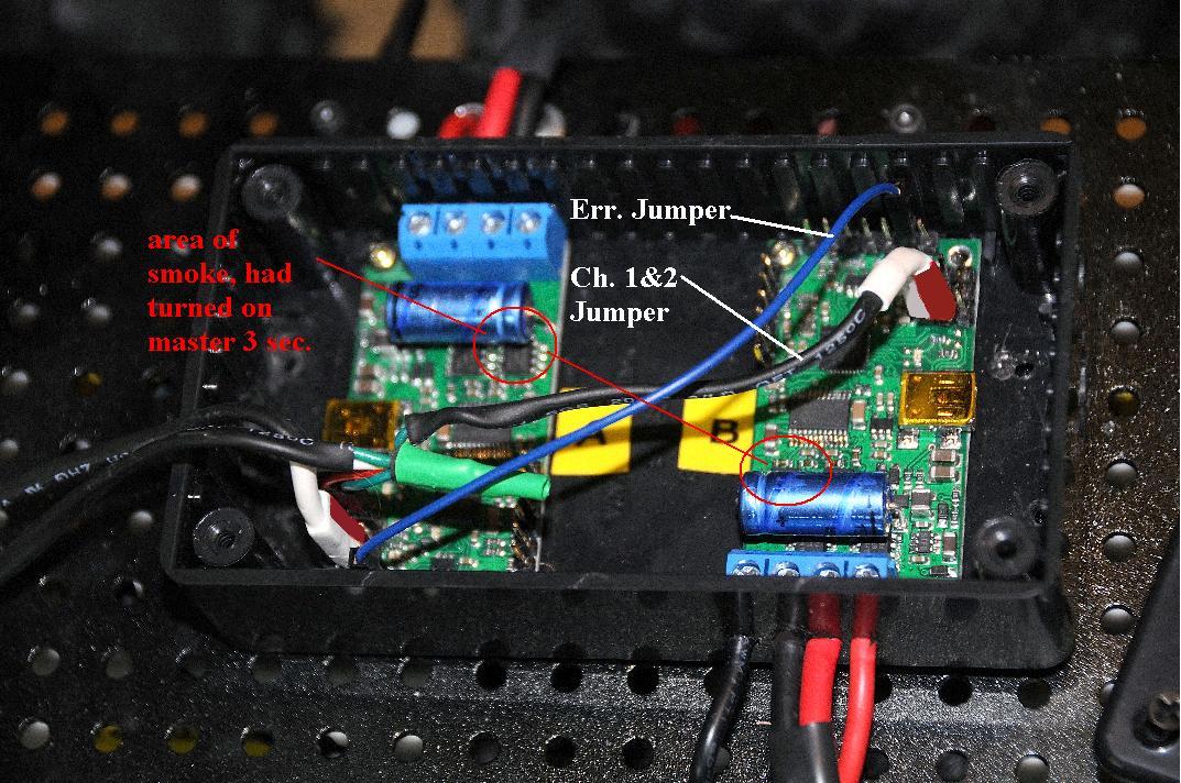
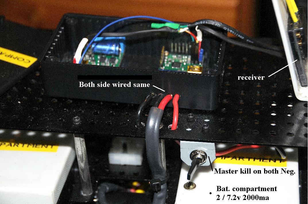
sorry for taking so long , death in the fam. I used the simple 18v15. But there has been a new developement, I connectted up according to instrucsion and today when I threw the master both board began to smoke by the capasitor. The only thing I had different this time was I had a seperate battery for each controller. I had my neighbour who is a helicopter engeneer have a look at my wiring and he is stumped to. Any thoughts Ben
There’s no need at all to apologize. My condolences on your loss.
If you still have your boards wired up the way they were when the trouble started, can you post some pictures so I can take a look? Is it possible for you to be more specific about where the smoke came from? Was it from the capacitor (I assume you mean the large blue axial capacitor) or from a component near the capacitor?
- Ben
Thank you Ben. I have enclosed 3 photo’s that I think cover it all, I appreciate your help muchly! Not sure of these photos as when I prev. they are chopped? Bill
Thank you for the pictures, they are very helpful! (They appear chopped to keep your post compact, but people can click on them to see them at full size.) If your battery leads follow the standard convention of black for ground and red for power, then you have power to your simple motor controllers connected backwards, which would certainly explain why both controllers smoked when you applied power. Can you verify that this is indeed the case? If so, I think there’s little hope that the boards are salvageable, but I might be able to get you a discount on replacements.
- Ben
The color code is right and have attchd the scmh. from the pdf file. Your saying the outside red and black should have been reversed?
Ben I connected up both boards to the smc center via usb and your right they are toast, but why should I maybe get a discount on replacments if I screwed up? Thanks, Bill
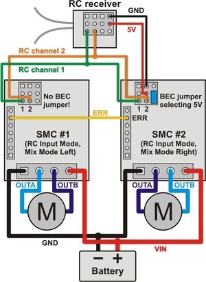
That is just a general wiring diagram that shows what pin (by name) connects to what. It is not specific to any particular device, so you definitely should not be going by pin location in the diagram; you still need to pay attention to how the wiring diagram translates to your particular Simple Motor Controller (we have three PCB versions, all with slightly different pin locations). The closest direct match to that wiring diagram is the 18v25/24v23:
The pin locations are slightly different on the 18v15/24v12:
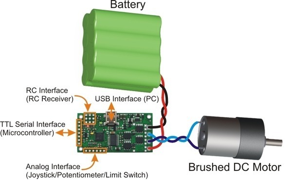
This is why the user’s guide has very explicit, board-specific diagrams at the top of each “Connection” section, including Connecting Power and a Motor.
To answer your last question, we want our customers have a positive experience with our products, and we are still willing to work with them even in the cases where the problem the result of some accidental misuse on their part. You can contact me directly at ben at pololu dot com if you want me to look into getting you a discount on replacements.
- Ben
Thank you very much for all your help, still not coming clear to me so I need to do some reading, Bill