I will attach a 14.8v / 4s / 10c / 1000 mAh Lipo battery to this driver.
As we al know the voltage across the battery may vary.
I will be using a brushed DC and it will constantly turn CW/CWW in a sero type application.
Cut off Voltage: 12 V
Nominal Voltage: 14.8 V
Maximum Voltage: 16.8 V
The maximum current draw will be 8A.
In the documentation states the following:
For good performance, it is very important to install a
large capacitor across the motor supply and ground close to the motor
driver. We generally recommend using a capacitor of at least a few
hundred μF and rated well above the maximum supply voltage; the required
capacitance will be greater if the power supply is poor or far (more
than about a foot) from the driver, and it will also depend on other
factors like motor characteristics and applied PWM frequency. A
through-hole capacitor can be installed directly on the board in the
holes labeled ‘+’ and ‘−’ (connected to VM and GND, respectively). The
driver includes an on-board 150 µF capacitor, which might be sufficient
for brief tests and limited low-power operation, but adding a bigger
capacitor is strongly recommended for most applications.
So what capacitor should i use? I’ve read capacitors do have tolerance of the voltage they can take?
So too high and too low V rarting is not a good idea?
For your setup a 25V, 560uF capacitor sounds like it would probably be enough, though like the note you quoted says, some parameters that you did not give like distance between the driver and battery and PWM frequency would factor in as well.
You mentioned that your motor will “constantly turn CW/CWW in a sero type application”. I am not sure exactly what movement you are describing, but if your system will be switching the motor from forward to reverse often, you will probably want to gradually decrease and increase the speed to prevent the motor from drawing large current spikes.
By the way, having a capacitor rated for a higher voltage is not generally bad, though it usually means a larger capacitor for the same capacitance value.
You mentioned that your motor will “constantly turn CW/CWW in a sero
type application”. I am not sure exactly what movement you are
describing, but if your system will be switching the motor from forward
to reverse often, you will probably want to gradually decrease and
increase the speed to prevent the motor from drawing large current
spikes.
Answer: Every second it will turn in the opposite direction.
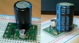
I soldered a 34V 1000 uF capacitor onto the board and put 14.8v on the board.
I did connect the battery wrong to the board
+(battery) to ground(Board)
-(battery) to Vin(Board).
But it should be reverse protected right? Then reconnected it properly
When i put 5V on the sleep pin with my arduino nothing really happens, i double checked with a multimeter and there is actually 5V on the SLP pin.
I guess i destroyed the board, or might shorted it in the wiring process… going to order a new one
Or is there a chance the capacitor i used is too Fat?
The G2 high-power motor driver 18v7 does have reverse voltage protection, but the capacitor you connected between power and ground is before that protection, so it sounds like at least the capacitor was damaged. Could you try removing it and seeing if the driver will work to just drive the motor forward slowly? A 34V, 1000uF capacitor is probably more than enough, but I don’t think it would hurt the situation, so if the driver does still work and you have another of those, you could use it.
If the driver does not work, I can help you troubleshoot. Did the driver ever work? If so, were you commanding it to switch directions every second? Is the 8A maximum you mentioned the stall current of your motor? Could you post pictures of your setup that show all connections?
I’m waiting my 18v17, it’s in the customs… While waiting, I was observing your conversation and it raised question on my mind:
On 18v17 page it said “For good performance, it is very important to install a large capacitor across the motor supply and ground close to the motor driver.”
There was also: “A through-hole capacitor can be installed directly on the board in the holes labeled ‘+’ and ‘−’ (connected to VM and GND, respectively).”
Q1: If I would like to add this additional capacitor on my own pcb, should it be between VIN and GND ? I was planning to leave VM unconnected in my implementation.
Q2: What’s the relation of pins VM and VIN ? Additional capacitor is between VM and GND if it’s soldered on your pcb, but still it’d be between VIN (main motor power supply connection) and GND. Am I lost ?
I have blown 2 boards of this type one by being un careful with probing 3V3 and VM and shorted it and another one with unkown reasons. Be care-full It will destroy the circuit instantly!
The two ± & - configurations are for a radial or axial capacitor. Which is just the physical layout of the capacitor.
Q1: an additional capacitor on top of the one you NEED to install is not necessary.
I think the only thing that makes sense i think is putting a fat capacitor on the board, i use 1000 uF rated for 35V. Because my battery power is 12-16.8V
I only use the following pins for control:
SLP
PWM
DIR
Yeah, my intent is to leave 3.3 Vout and VM untouched and I was wondering does the additional capacitor will effect if VM is unconnected and the capacitor is soldered on 18v17’s (+) and (-) pins or could I install it to my own pcb between VIN and GND instead ?
I’m going to control linear actuator with it. I’m doing PID and pwm functions with Arduino Due… Maybe some day I’ll purchase something like 21v3…
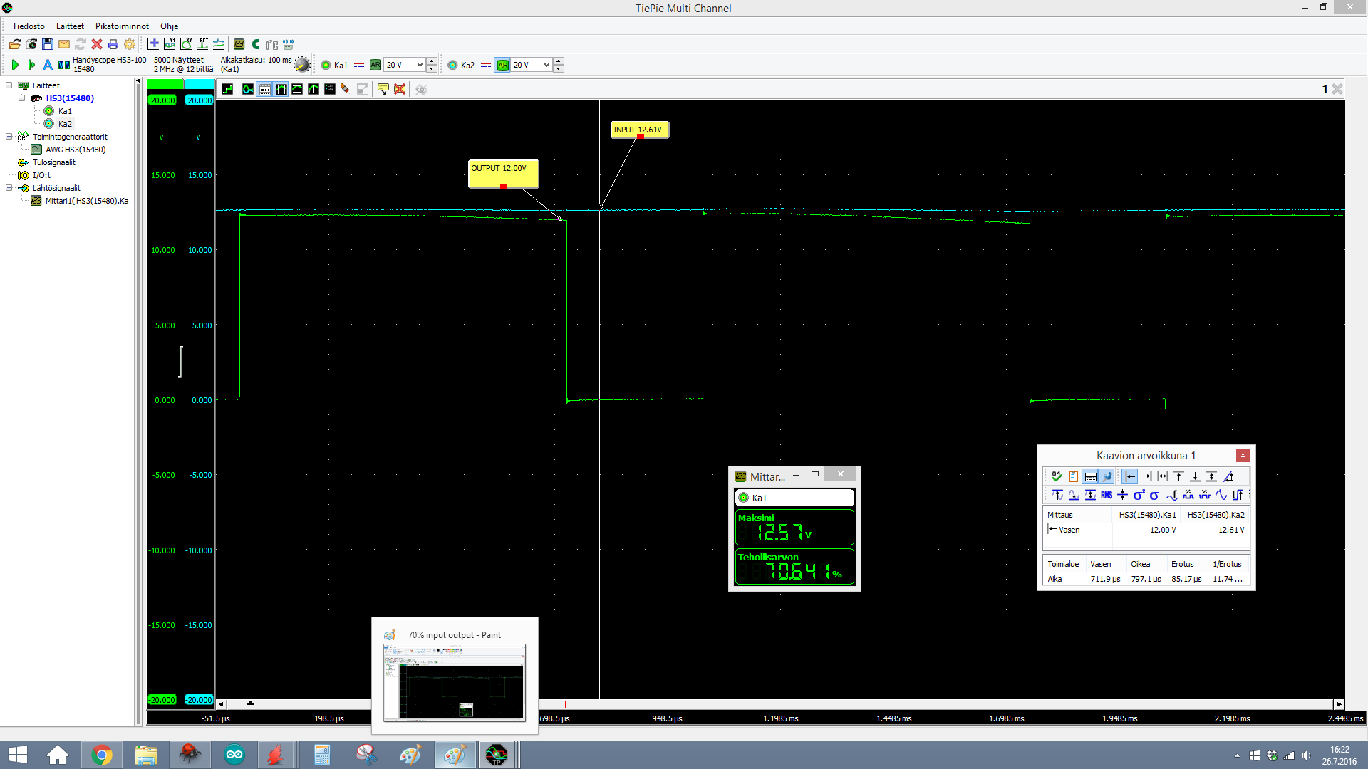
You could connect the positive side of your capacitor to either VM or VIN. Connecting the capacitor to VM is safer though, since VIN is just the input voltage, and VM is the input voltage after the reverse voltage protection circuit. The pictures you posted make it look like you soldered your capacitor into the + and - pins, which are connected to VM and GND; that should be fine.
I haven’t soldered it yet, it was just as example for the picture, but I’m going to solder it to the (+) and (-) on the 18v17 board (like it was in the picture). Would it be even better if I have one on your board and one one on mine, between VIN and GND ?
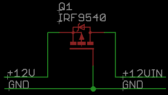
CharlieK:
Speaking about your problems with polarity, this is quite simple polarity protection circuit I’ve used for some time now. You only need one P-channel MOSFET (I’ve have used IRF9540N) for that. It could handle more current that circuits made with zener and resistor and also this doesn’t need that resistor which also create some voltage loss.
Generally, it does not hurt to have more capacitance on the input, so you could add another capacitor to your board, but I think that the one you have now is probably fine by itself.