Hi,
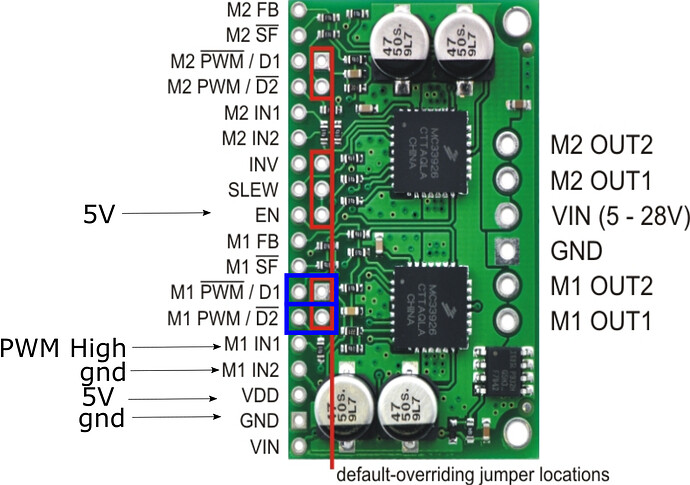
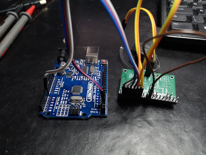
I amtrying to set up this board with an arduino UNO, I wanted to use PWM on in1 and in2 directly. To test I connected up for just one motor. I am going to use jumpers on the D1 and D2 pins (shown with a blue box) where D1 will be brought low and D2 will be brought high so that I can use the PWM in1 in2 mode. I will then enable the EN pin with 5v and I will drive it by sending PWM to IN1 while keeping IN2 at ground
All seemed good until I started outputting different PWMs and the output got weird:
VIN is 12V
I have the multimeter connected to M1out1+ M1out2-
pin2 is set to PWM
pin3 is set to PWM
pin2 analogWrite(0)
pin3 analogWrite(0) 0.0V
pin3 analogWrite(100) 7.3V
pin3 analogWrite(200) 10.5V
pin3 analogWrite(255) -12.V ???
and then I switched the pins…:
pin3 analogWrite(0)
pin2 analogWrite(low) 0.0V
pin2 analogWrite(100) 0.0V
pin2 analogWrite(200) 12V
pin2 analogWrite(255) 12V
So it is responding to PWM input but not in the way I expected!
Have I wired something wrong in wiring it up? I checked the PWM output and it looks fine, I also put a resistor across M1out1 and M1out2 to simulate a motor load, still nothing.
any help would be greatly appreciated!
void setup() {
// initialize digital pin LED_BUILTIN as an output.
Serial.begin(9600);
pinMode(LED_BUILTIN, OUTPUT);
pinMode(2, OUTPUT);
pinMode(3, OUTPUT);
}
// the loop function runs over and over again forever
void loop() {
analogWrite(2, 0);
analogWrite(3, 0);
Serial.println(“low”);
delay(2000); // wait for a second
analogWrite(3, 100);
Serial.println(“100”);
delay(5000); // wait for a second
analogWrite(3, 200);
Serial.println(“200”);
delay(5000); // wait for a second
analogWrite(3, 255);
Serial.println(“255”);
delay(5000); // wait for a second


