I have a problem with my VNH5019 shield which i´m using with an Arduino Mega2560. I supply the shield with 13.8V from a power supply and a DC motor is connected to M1A and M1B.
M1EN/DIAG = 5V
M1INA = 0V
M1INB = 5V
therefore M1B = 13.8V all the time
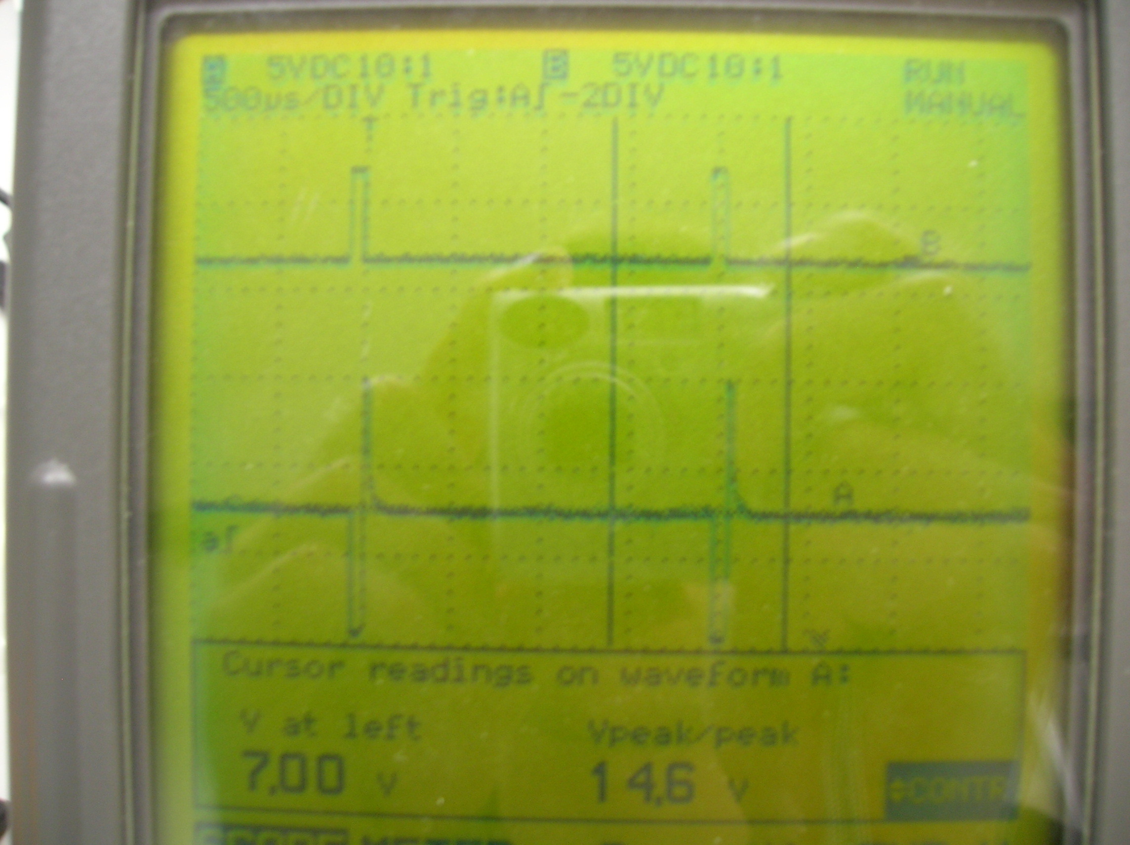
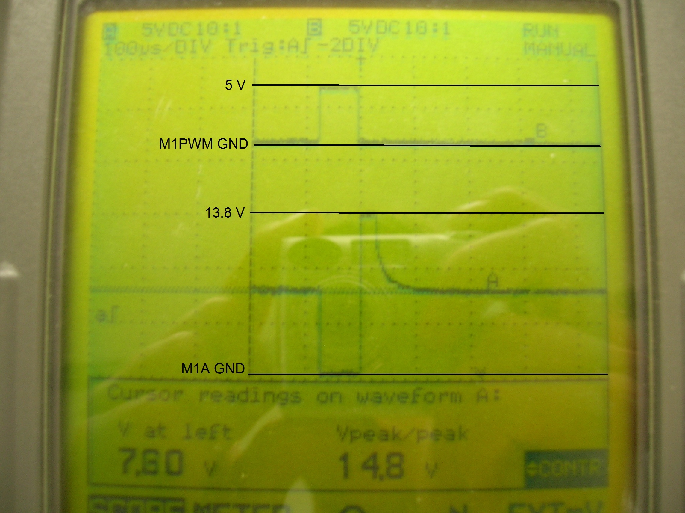
The problem occurs for M1A, it doesn´t stay at 13.8V when M1PWM is low but drops to a lower voltage shortly after M1PWM changes to 0V. Therefore my motor is running faster than it should.
I hope this pictures shows what I mean.
If I increase the duty cycle of the PWM the drop gets bigger and bigger. This means if i want 1V RMS output i get about 10V RMS.
This problem occurs for both channels of the shield.
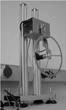
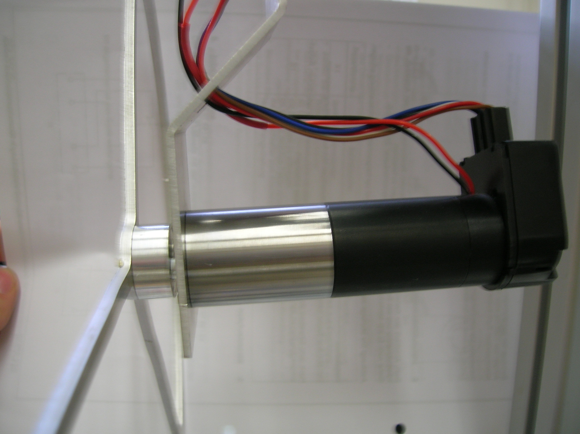
Okay maybe some more information about my application: I´m building a flywheel pendulum and the flywheel is driven by a small motor (https://fmcc.faulhaber.com/resources/img/EN_2642_CR_DFF.PDF) via a gearhead (14:1). This motor is supplied by the driver shield.
I discovered now that if i stop the flywheel with my hand so it can´t spin everything seems fine. It looks like the more current the motor draws the better it gets.
Wheel spinning: Current = 60mA Voltage = 7V RMS
Wheel not spinning: Current = 200mA Voltage = 0.5V RMS
Another thing I tried is to put a resistor parallel to the motor in order to get a higher current. This also lead to a better result.
Is there some kind of minimum current that needs to be drawn from the shield for it to work properly? Maybe for the MOSFETs in the output drivers? I searched in the datasheet of the VNH5019A-E chip but found nothing.
Those look like typical waveforms for an H-bridge controlling a DC motor, and I am not sure what you mean when you say that your motor is “running faster than it should”. Could you explain what you expect to happen compared to what is actually happening?
By the way, you should not need to add a resistor in parallel with your motor. This is likely to waste a lot of power and make your system much less efficient.