Apologies about posting such a basic question, but I’m having some trouble using my Raspberry Pi 2B with a VNH5019 motor driver carrier. I simply want to control the speed of my motor using the hardware pin on the Raspberry Pi PWM1 pinout (GPIO pin 23, header pin 33, see all pinouts).
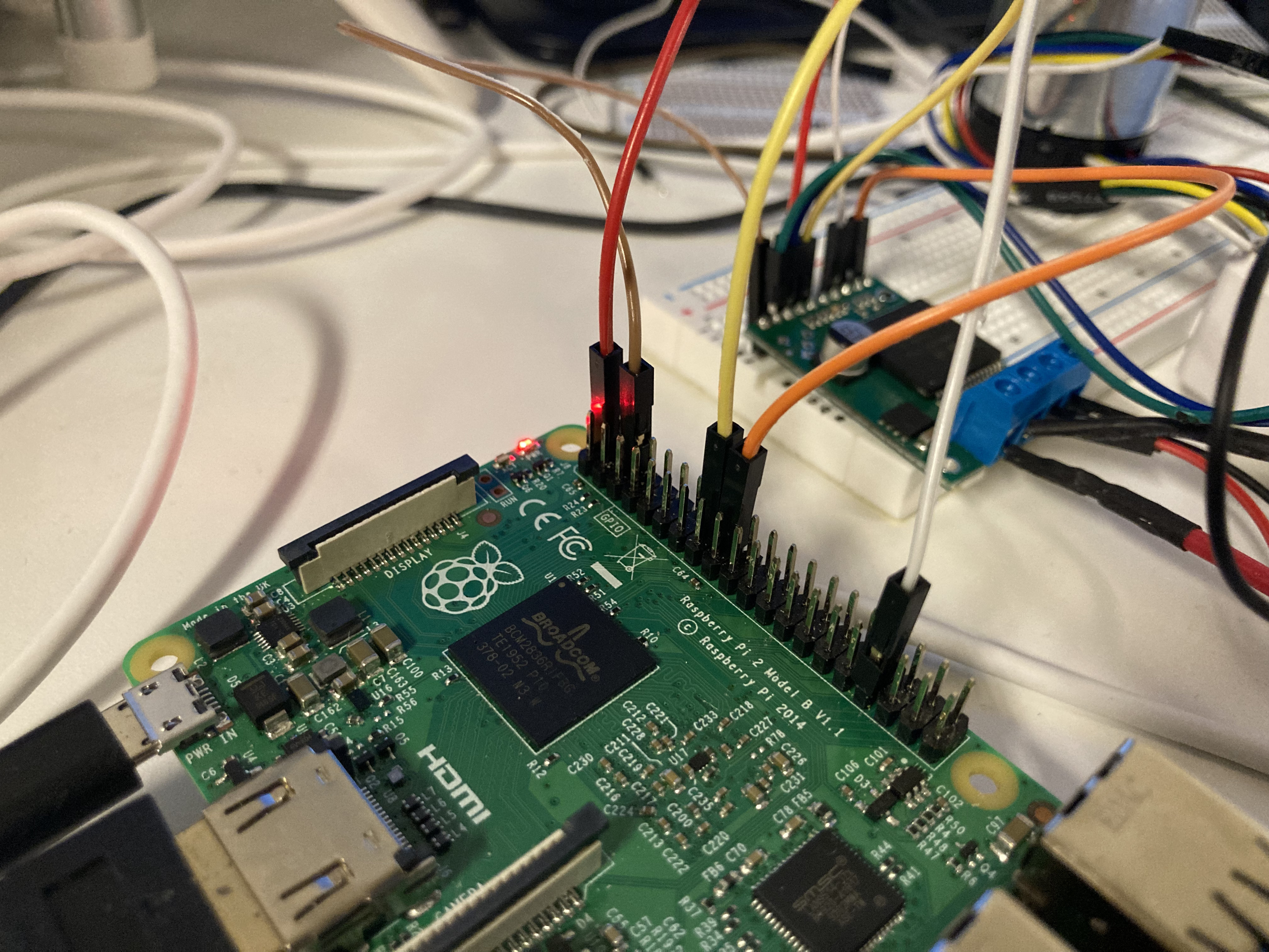
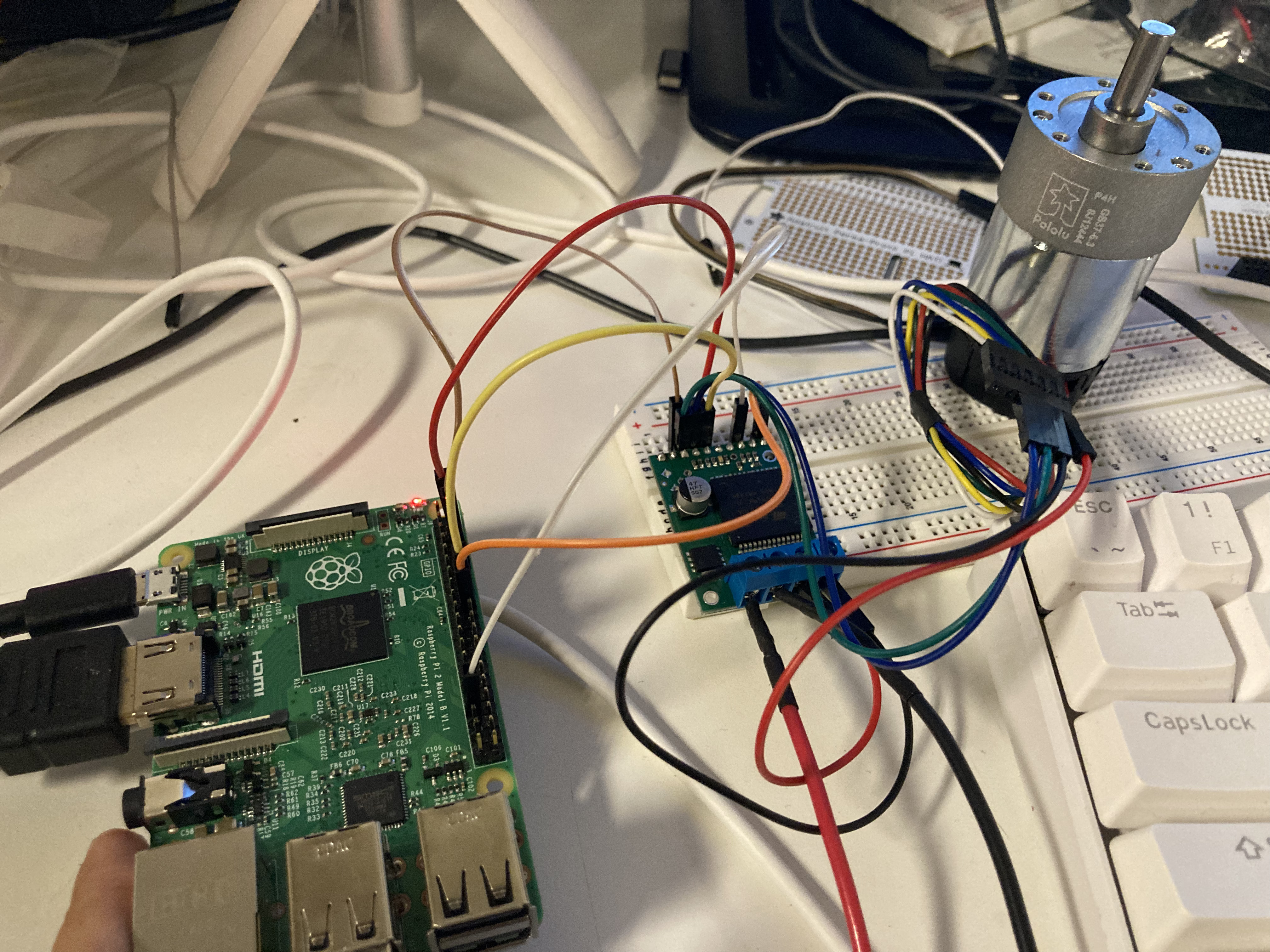
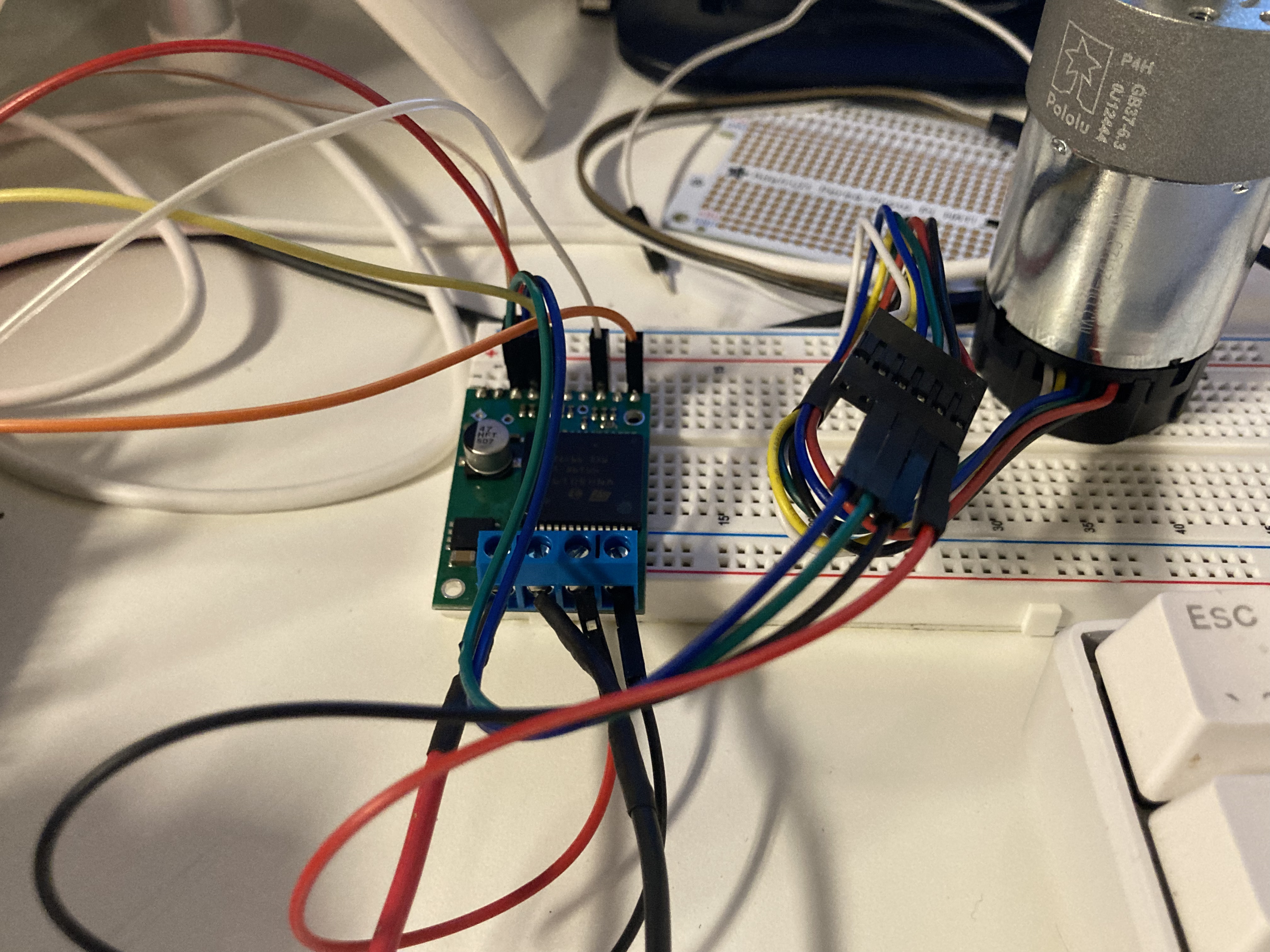
I have connected the power for my motor to the OUTA and OUTB pins on the VNH5019, and the board is connected to a 12V 1A power supply. Also, the INA and INB are connected to RasPi header pins 16 and 18 respectively. The PWM pin on VNH5019 is connected to RasPi header 33 as mentioned above. I’m also giving 5V logic power and ground from the RasPi to the VNH board. I have attached a few picture of my setup.
I have been trying to use the wiringpi library and the pwmWrite function, but I never get any rotation in the motor. Alternatively, when I just output a constant HIGH signal to the pin, the motor will spin at max speed just fine. Not sure what i’m doing wrong, but if you know of any ways to control the speed of the motor with the VNH5019 and a Raspberry Pi, I would love any guidance. I’ve also included my code for reference.
I have also been playing around with the DRV8835 Raspberry Pi library, which seems fairly straightforward and I don’t understand why the same code approach isn’t working in this case.
Thank you so much, always appreciate how helpful everyone on this forum is.
motorTest.py (1.2 KB)
Hello.
It looks like you are using the wrong pin numbers for your control pins. Since you called wiringPiSetupGpio, your PWM pin (Motor1Ewpi) should be GPIO 13. It looks like you might have had that at one point with your unused Motor1E variable.
If you want to use the wiringpi numbers, you should use wiringPiSetup instead. You can find more about the different setup functions on this reference page for wiringpi.
Brandon
Hello,
thank you so much for you help. I just fixed the issue and it works great now!
As I continue with this project, would you happen to have any tips/suggestions for the best way to read the rotary encoder information through the Raspberry Pi?
Thanks!
I am glad to hear you got it working!
Unfortunately, the Raspberry Pi is not very good with timing-sensitive applications like reading quadrature encoders. If you want reliable readings, one solution might be to add a separate microcontroller such as an Arduino or one of our Arduino-compatible A-Star controllers that can read those encoders and relay the information back to the Raspberry Pi. However, please note that most of our controllers operate at 5V while the Raspberry Pi operates at 3.3V, so you would probably need a logic level shifter as well. The A-Star 328PB Micro has a 3.3V operating voltage, and is very compact, but it does not have built-in USB functionality, so you would need a serial adapter like this USB AVR Programmer to program it.
Brandon