I have bought the vnh5019 motor driver board from pololu. At the moment i’m trying to test the board and i have a problem with the duty cycle. The input voltage to the motor is not varying linearly with the duty cycle provided from the pwm input. I’m supplying 24v to Vin. At 10%duty cycle i already have about 17v on the motor. At 50% it is almost equal to 24V. Do you have any idea why this is happening? Thanks in advance for your time and help
Most meters do a poor job of reporting an average or root mean square value of a complex waveform, which is what is present across the motor terminals during PWM. The important thing is whether the motor shaft rotates at a speed which is approximately proportional to the PWM setting. Is that the case?
If you have access to an oscilloscope, check the waveforms on the motor for various PWM settings. You might give some details about the motor you have, as well.
I agree with Jim: an oscilloscope would really help get to the bottom of this. However, if you do not have access to an oscilloscope, I suggest you take a look at your PWM code as I suspect the duty cycle is not what you think it is. What are you using to generate the PWM signal?
I am using an oscilloscope to read the pwm signal…to test the board i am simply using a signal generator which provides a pwm signal with variable duty cycle. Even INA/INB i’m inputting them manually to simplify the analysis and avoid any chances of error from my part. I am using an oscilloscope to check thal all the inputs are correct.
I am managing to change the direction of the motor’s rotation using INA and INB
I am also observing that the speed of the motor is increasing the the duty cycle but not as it should be. I’m supplying 24V. At 10% duty cycle i already have 17v on the motor. And at 50% almost 24V…so it already at full speed.
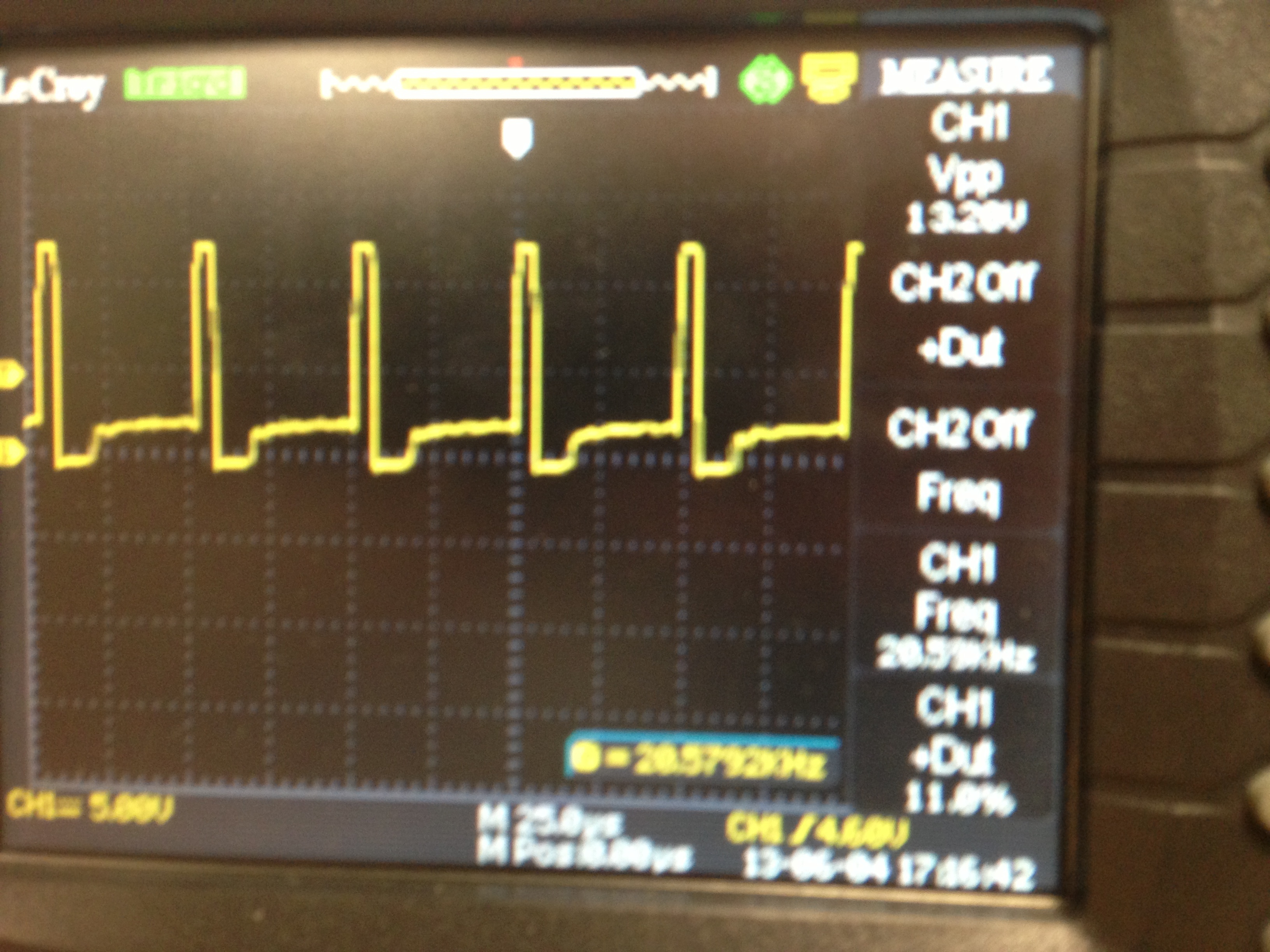
The figure attached shows the waveforms across the motor. As it can be seen there is the pwm signal but there is also a variable offset voltage added to the pwm. During testing i noticed that this offset increased with the speed. This offset leads to a nonlinear relationship between the speed and the pwm’s duty cycle which:
has 17v average across the motor at 10% duty cyle (which in reality should be near 2.4v if we are using a 24v supply)
reaches saturation (almost full speed) at 50% duty cycle.
Can someone please help me solve this problem?
That waveform does not at all match your description, though the general shape of it is exactly what we would expect. Can you post some oscilloscope captures corresponding to your claims of a 17V average at a 10% duty cycle and a 24V average at 50%?
By the way, be careful about measuring across the motor with just a standard probe and grounding clip, as you could be inadvertently shorting one side of the motor to ground.
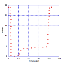
For an exercise I digitized the photo to approximate a cycle of the waveform, as shown below. I assumed that the voltage supplied to the driver is 24V, although this does NOT agree with the peak voltage indicated as 13.2V on the scope face.
The duty cycle is measured at about 10% and (assuming 24V to the driver) the average voltage across the motor terminals is about 10.6 V. However I believe that the rise to 4.0-4.5 V in the time period 150-380 pixels is due to freewheeling, where you are measuring the voltage generated by the motor. In short, this waveform is exactly what you expect for a properly functioning motor driver.