Hi -
I plugged in the VNH5019 shield, uploaded the code and powered it on using USB power to the Arduino and 12V. M1 did not work, but M2 appears to work fine.
I can not find any documentation on what the LED’s mean other than the cryptic statement under Features on the datasheet - https://www.pololu.com/docs/0J49/1.a
“Motor indicator LEDs show what the outputs are doing even when no motor is connected”
Heres a video with some LED’s of colors and unknown meanings for the powered up board -
This is a for a project, so I need to know asap if I have a defective part. Thanks.
Very likely, you have a wiring error, a code error or a defective motor. Double check all your connections for continuity and proper contacts. Swap motors (with power off) to see the problem follows.
Please post a hand drawn wiring diagram (with pins labeled), the specifications of the motor power supply and the motors, and the code.
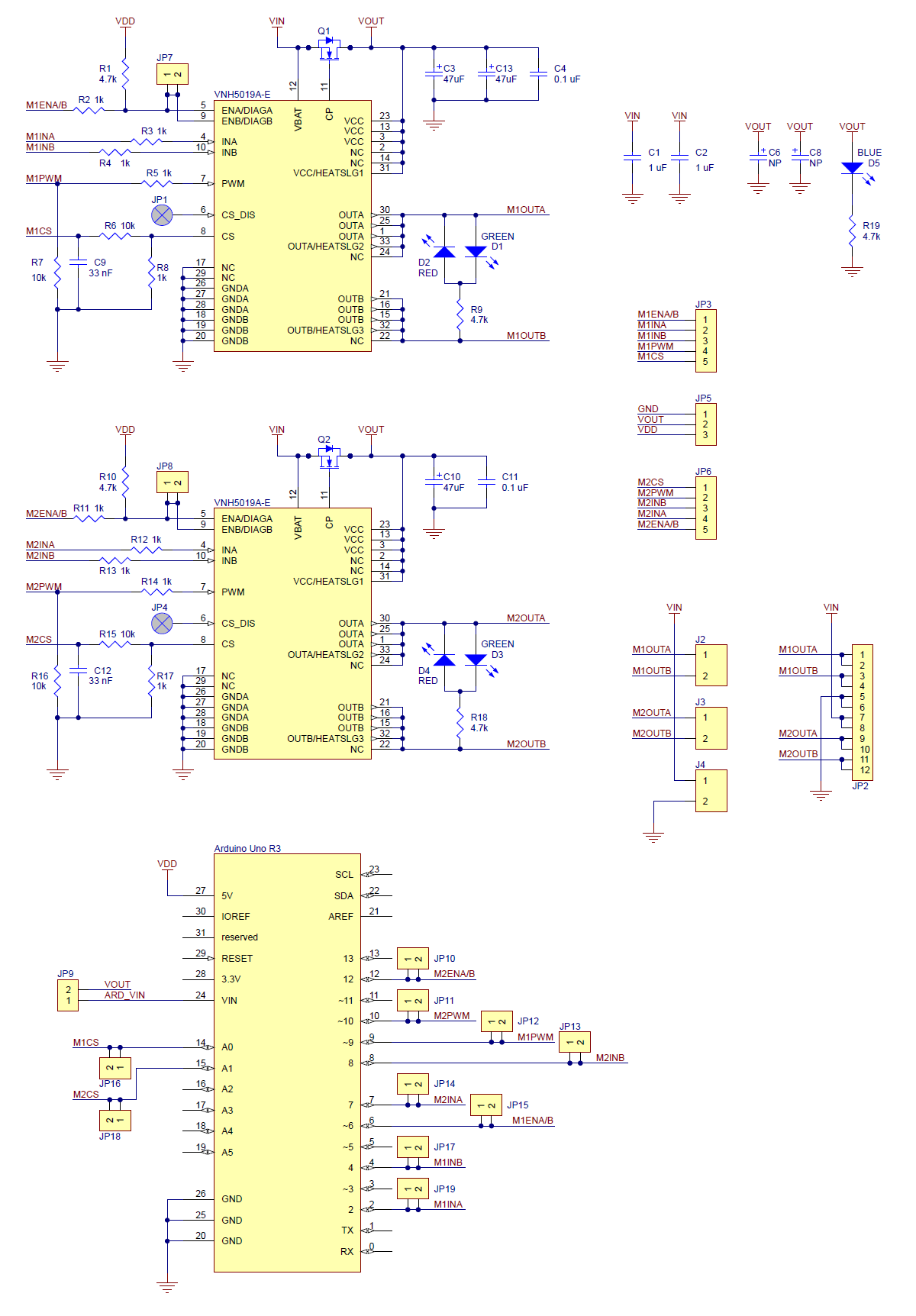
As a quick look at the motor driver schematic shows, for each output, the green LED lights if the motor A output is positive and B output is negative. The red LED lights for the reverse case.
I tried on 4 different motors, each was tested to work using a regulated power supply so I am confident the motors are fine.
The code I used was the demo code provided (in the github)
For the motors, what does a flashing yellow LED mean? I don’t see yellow on the schematic?
Additionally, for the motor outputs (even for the M2 that worked) I never saw a red LED, only green and yellow. M1 LEDs never let up.
Also, I should point out - The LEDs next to my motor outputs are D1,D2,D3,D4, but the schematic (https://a.pololu-files.com/picture/0J5220.1200.png?3f822e0f830bafc2168f106f9733350a) lists them as D2,D3,D4,D5 (This is visible in the video as well). D1 is red, but I think it’s supposed to be blue according to the schematic?
The connections in the photo you posted sure look flaky. Alligator clips? Come on.
The VERY FASTEST AND SUREST WAY to destroy a motor driver is to disconnect, or have a lead come loose when the power is on.
Post the demo program serial monitor output and links to the motors, and their specs.
I’m literally asking what the LEDs mean because the colors I’m seeing don’t correspond with the schematic or documentation.
Even the instructions say I don’t need it to have any motors to test that the LEDs are working properly (3.d) https://www.pololu.com/docs/0J49/3.d
But you stated that you have already connected “4 different motors”. I would guess that with such loose, possibly intermittent connections, or by making changes with the power on, one or both of the drivers has indeed been destroyed.
We have all made mistakes like this, so chalk it up to a learning experience.
Thanks, I have been informed I have a counterfeit item by someone at the company that took time to actually watch the video and focus on facts rather than ‘flaky alligator clips’.
Who knows? The clone might have worked properly, until damaged by loose wiring.
