Hi all,
I have a VNH5019 Shield connected to an Arduino Leonardo. When I DO NOT have the motors connected the motor, leds are lighting up. The voltage provided to VNH5019 is 7.6V LiPo battery, while Arduino is hooked to my computer USB(no power jumper used).
When I DO connect a motor , suddenly the motor led is turned off and the motor has a “jerk” reaction for only a fraction of a second.
It sounds like a power issue. Is your battery fully charged? If not, the battery voltage might be dropping too low when you try to run the motors, causing the shield to shut down. Also, you might try ramping up the speed instead of starting at max speed. Could you try running the demo code we provide after your battery is charged?
Hi,
The battery I think it’s ok, since conected directly to the motors get them to spin ok. Also switched to a 11.1V battery.
I’ve uploaded the program, removed the part about m1 since I’ve not connected anything on m1 and would always return fault on m1 and left only m2 where I get:
M2 current: 204
M2 fault.
I’ve observed that even with the motors not connected I’m always getting the fault message.
pinMode(6,INPUT_PULLUP);
pinMode(12,INPUT_PULLUP);
with motors not connected it runs not reporting any faults, but when I connect them, I immediatley get a Mx fault.
Has your shield always had this behavior, or have you gotten it to work in the past?
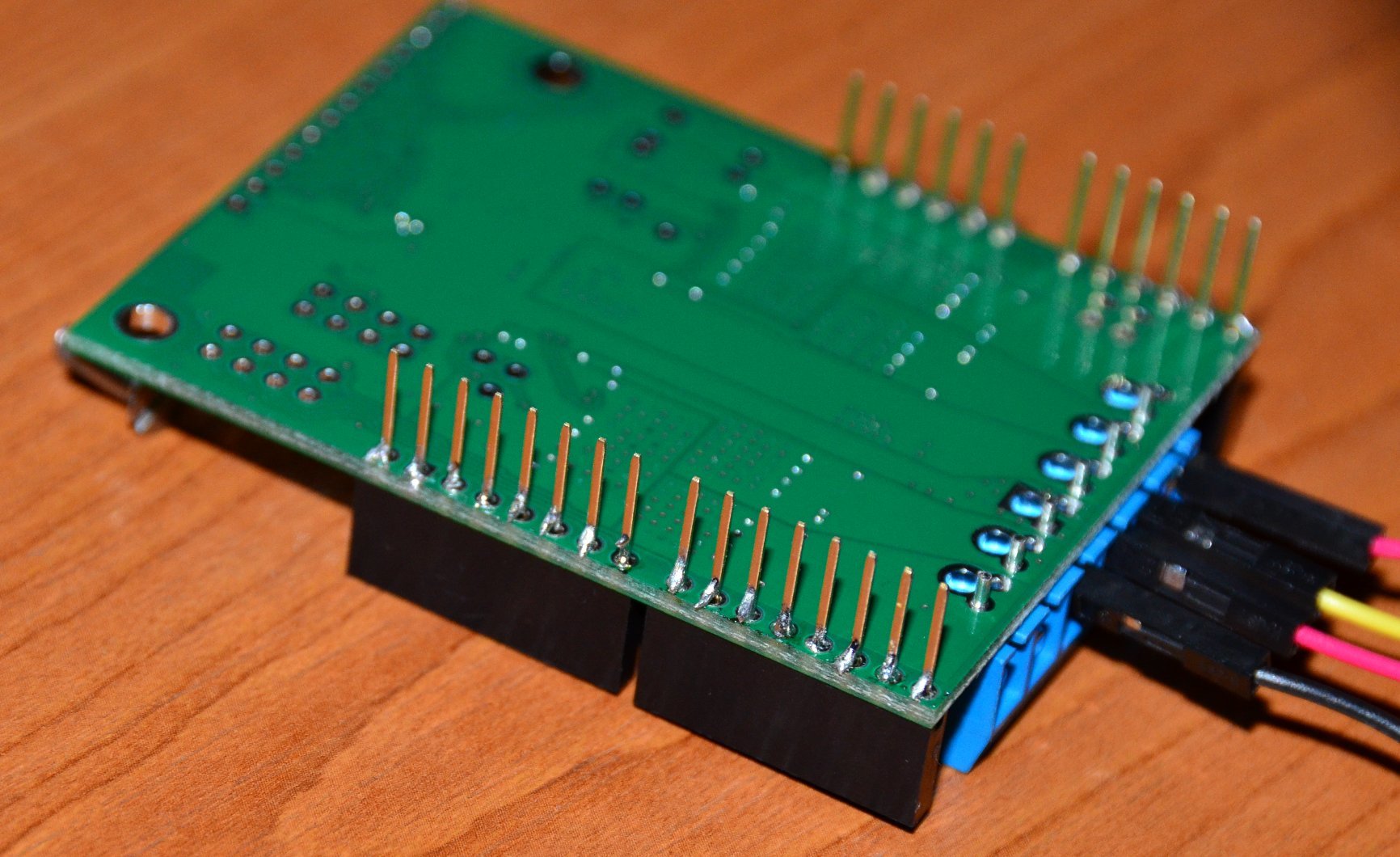
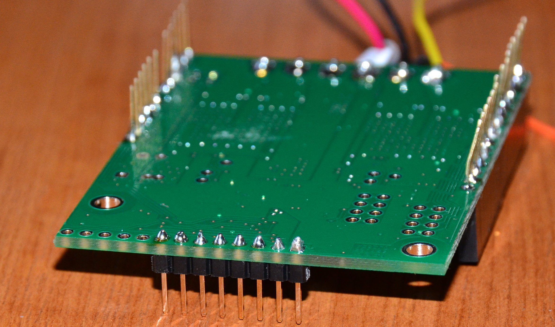
You should not need to add input pull-ups to those pins in your code since there are already pull-up resistors on the shield. The unaltered demo code should not return a fault when you run it with no motors connected. Could you post pictures of your setup and the underside of your VNH5019 shield?
Also, you should still check to make sure the battery is fully charged. If the voltage drops below 5.5V, the motor might still run when you are connecting it directly to the battery, but the VNH5019 shield will not.
Hi Brandon,
I did not know it’s supposed for the example to work with no connections. Thought that when no motor connected it’s supposed to report motor fail. So I tried to simplify and not even connect the motors and just tried to make it run the example.
So I changed nothing except added a delay(10000) to be able to setup the serial monitor after Arduino reset and print also the “i” for each loop.
Unfortunately I don’t know, everytime I think I found a consistent behaviour to report it behaves different. The most I got was to make it to before the last for cycle(i=-400) for m2 when it reported m2 fail.
Lately stops at first i=0 or i=4 m1 fail.
Shield is new, first time I work with one(I mean it’s not the case that I ever got one working and it suddenly got to this state).
Thank you for posting the pictures. The inconsistencies you are getting in your test reinforces my concern that it is a connection issue. Almost all of your solder joints look like they are not making a good connection. Could you try re-soldering the header pins? When you are done they should look like the ones in these soldering tutorials.
Also, I cannot tell from your pictures if you have the blue terminal blocks soldered to the board. If you do not have them soldered yet, these terminal blocks should be soldered into the larger holes (instead of the smaller 0.1" holes they are in right now). You should make sure these are making a good connection as well.
Hi Brandon,
I soldered the blue connectors into the big holes, also did some resoldering on the headers. Now the programs runs flawlessly top to bottom but still have problems with real motor connected. Meaning it’s doing the jerk thing and it’s lights out without it or any other leds coming back on - I even removed the fault check.
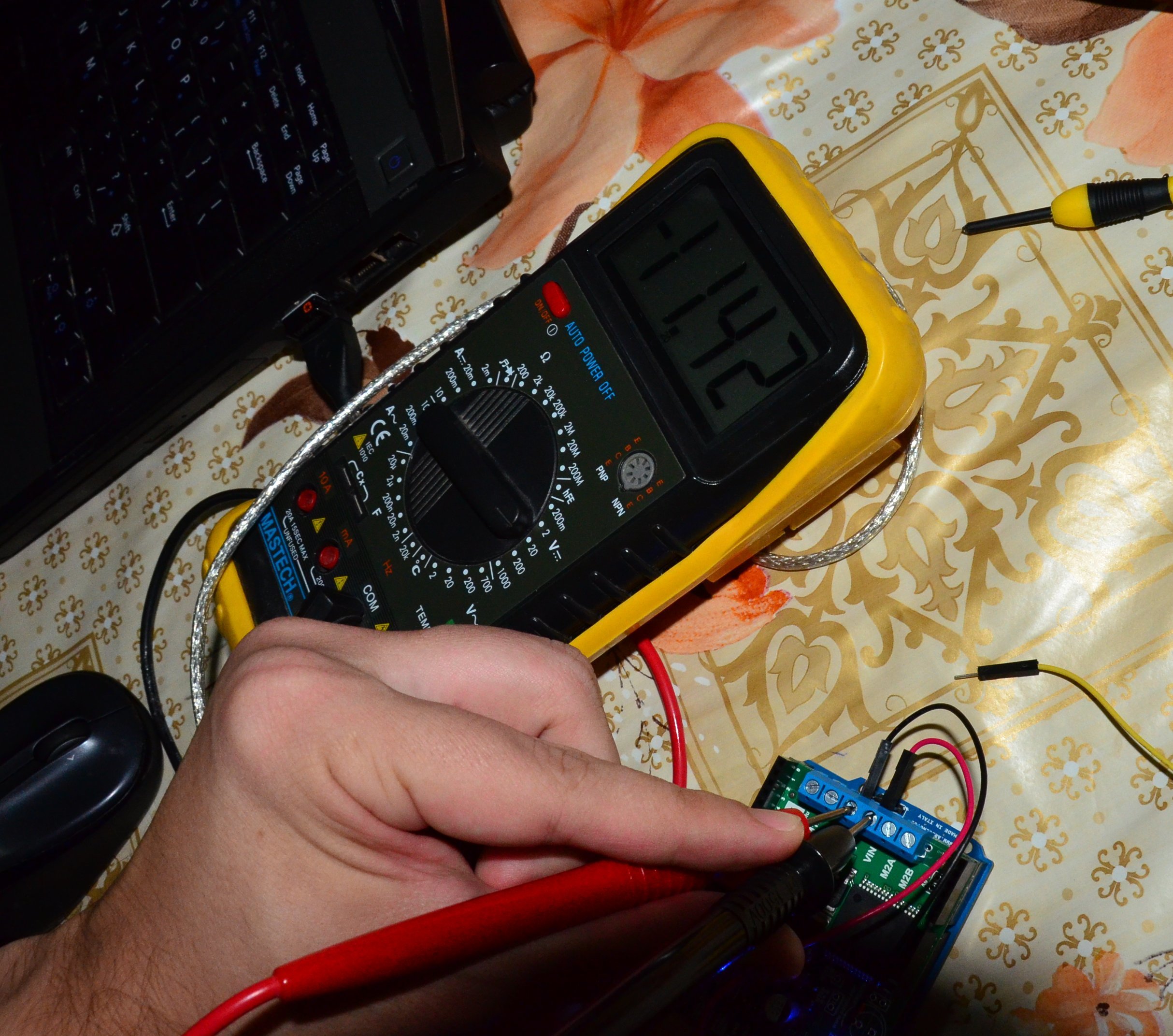
Without the motor, the voltage output between M1A and M1B is rising smoothly to 12V and back, measured with a multimeter. Should I add a resistor between M1A and the motor maybe, I mean could the motors by themselves sink so much current it’s triggering the driver into a protection mode? Motor is working ok with the battery connected directly to the motor’s terminals. I have a blown fuse on the multimeter for current measuring but will try to get it sorted to see the flowing current. Anyway if you have any input that might help, please don’t hesitate :).
The motor that you linked to in your first post should have a stall current of just over 3A at around 12V, which is much lower than the continuous current rating of the VNH5019, so the motor should be fine. You should not need to add any extra resistance to the motor. Did you receive any motor faults when you ran the sample code with your motor connected?
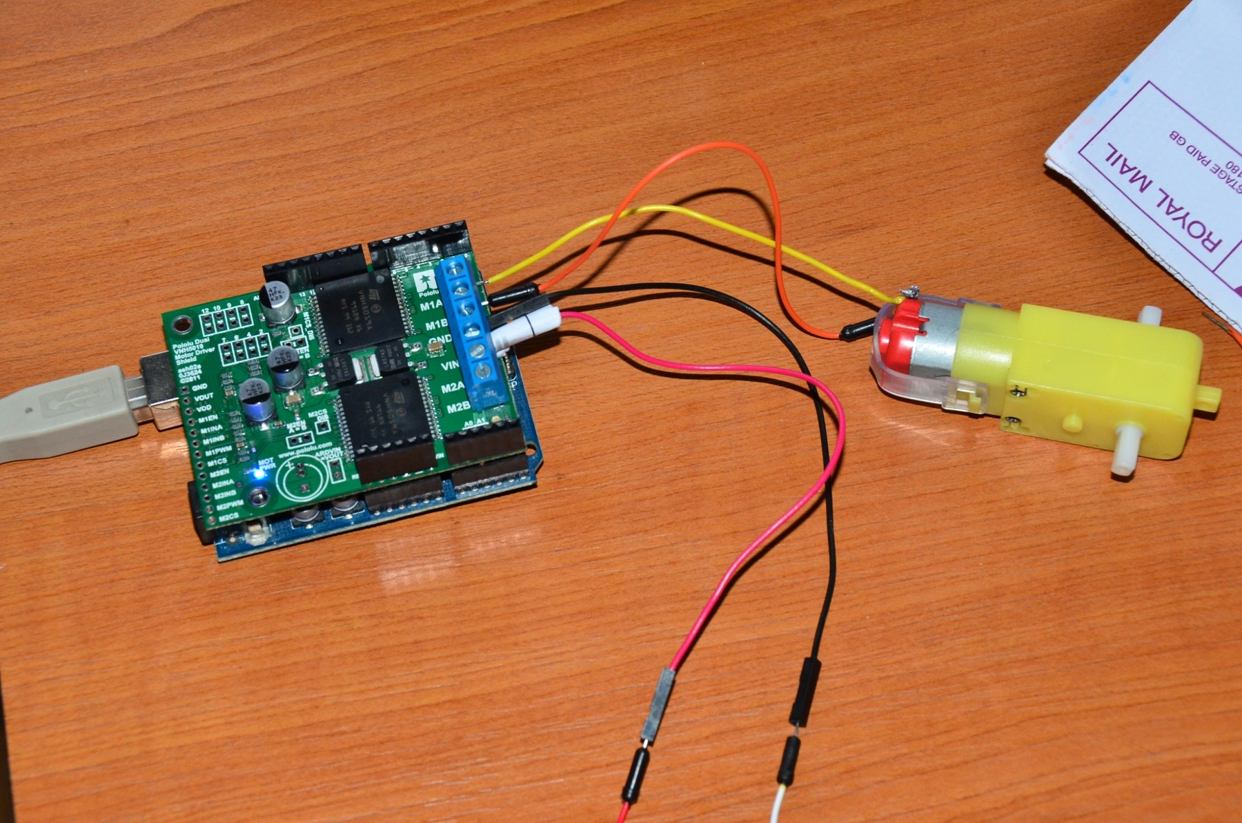
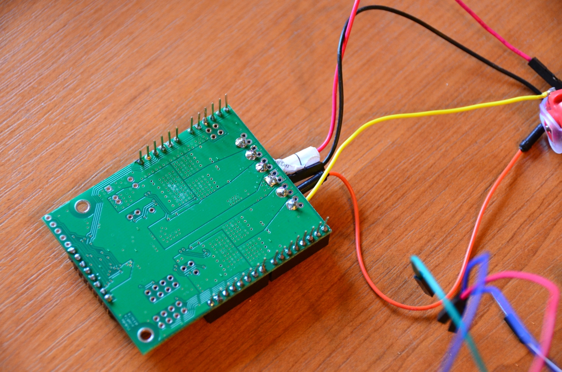
Could you post a picture of your entire system, including the motor and the connections from the VNH5019 shield to your motor?
Also, did you blow the fuse in your multimeter while trying to measure the current draw of your motor in this system?
Hi,
The blown fuse was back from college years, somehow I never got around to replace it till now. The multimeter is working ok, and yeah, I see something like 1.2A spike in the begining before it dies. But the same reading I get when motor directly connected to the battery.
I do get motor faults when the motor is connected:
Speed:272
Speed:273
Speed:274
Speed:275
Speed:276
M1 fault
What is strange don’t know if it’s a hint or not, when the motor was NOT connected, when motor fault happened, the led remained turned on, while when motor fault with the motor IS connected is lights out(power led remains active though).
Will try to come back tomorrow with a picture.
I don’t really understand the function of motor fault. What does it check is it a safety check since from there on it goes in a loop? Can it be removed entirely. I think I removed it in one of the tests but the leds and motor voltage did not come back online. Don’t know if it’s good or not to try removing the motor faults checks.
Are you still getting motor faults when you run the unaltered demo code with no motors connected? I was under the impression that after you fixed your soldering, you were no longer receiving faults when the motors were not connected.
The fault pin on the VNH5019 is also used as the enable pin, and when a fault happens, the driver pulls that pin low, which disables the driver’s outputs. Ignoring the faults will not keep the outputs from being disabled, and it is generally not good practice to ignore faults or errors. According to the datasheet, faults can either be caused by an overtemperature condition or the output being shorted to the motor supply. Information on the fault conditions and how to tell what fault is happening can be found on page 15 of the VNH5019 datasheet, which is located on the “Resources” tab of the driver’s product page.
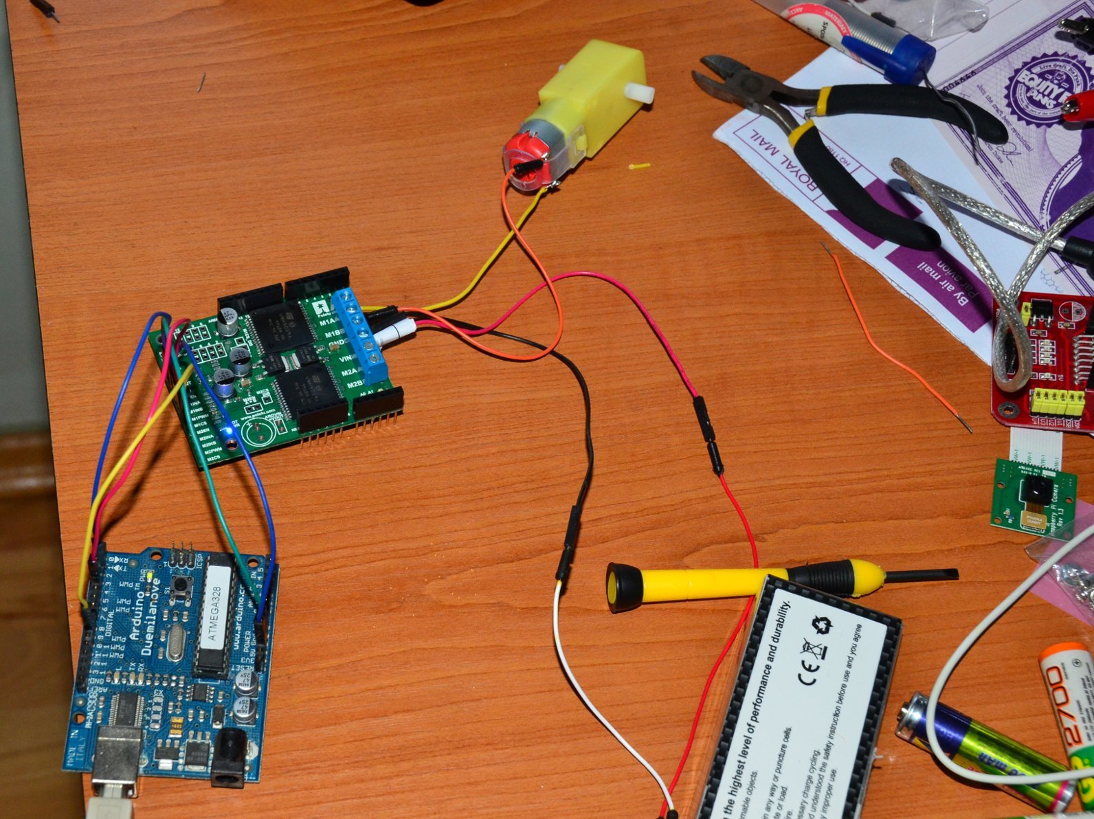
Seeing your pictures might help me figure out what the problem is.
I was thinking that maybe I can reduce the and I’ve attached the pins to be used as non shield mode.
Sadly I’m getting the same effect of the short motor jerk.
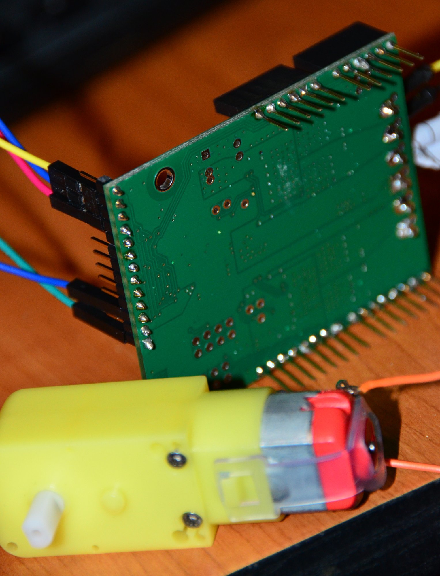
Thank you for posting more pictures. I did not notice anything obvious that might be causing a problem. Could you try connecting the motor leads to M2A and M2B to see if you get the same result?
Also, the motor you are using looks a little different than the one you linked to before. Are you sure the specifications you linked to apply to that motor? Do you have another motor that you could try?
By the way, when you have the general purpose motor driver pins soldered in and still use the driver as a shield, be careful that they do not touch anything on the Arduino that could cause a short.
About the motor, it’s true, actually bought them in a standard chassis and I’ve thought that’s what they put on it. Anyway it seemed it does not draw more than 1.3A and I was hooking them up to L298N motors and they were running ok, but I was preparing for some stronger 2A pololu motors hence the new driver.
All of the connections in your pictures look like they should work. I am starting to suspect that the board might have been damaged. If you contact us directly by email (support@pololu.com) with your order information and refer to this post, we can see if there is anything we could do to help you out with a replacement board.