Power will come from the top of the robot from 3x 18650 batteries in series, and I have a 15A fuse and power switch. I plan to put the motor drivers at the bottom near the motors. I expect the power leads from the battery to the motor driver to be about 40-50cm. The power leads are from my local electronics store and are rated for 7.5A - they don’t specify exactly what AWG they are.
The VHN5019 product page says that an additional capacitor is normally not necessary, but may be required for long power leads. Maybe this is a silly question, but would my power leads count as “long”, and thus require an additional capacitor?
Also, I read your page about LC voltage spikes, which is new to me. Is is likely that the existing capacitor on the VNH5109 board is sufficient to mitigate LC voltage spikes for the motor driver?
Whether or not you need an additional capacitor depends on your specific system. I would not consider 40-50cm leads short, but since the VNH5019 already has a electrolytic capacitor, I do not expect LC spikes to be a problem. However, since your motors might see pretty high accelerations and have to switch directions quickly in a balancing robot application, adding a capacitor with a few hundred microfarads still seems like a prudent precaution. If you have space for it, then I would recommend that. If you have tight space constraints, then you might try testing your system with a lower voltage (e.g. one or two batteries instead of all three) and monitoring it with an oscilloscope to gauge whether or not you should prioritize making another capacitor fit.
Thanks for your advice. I don’t have access to an oscilloscope, so I’ll follow your recommendation and add the capacitor. By space, do you mean vertical space above the motor driver? If so, there will be plenty.
My local electronics store has a 470uF 16VDC Electrolytic RB Capacitor. I know much about capacitor types - is that the right type? They also have a 220uF version if that’s better.
Yes, I was referring to the vertical space above the motor driver that the additional capacitor would need.
Yes, that is the right type of capacitor, but I would suggest finding one that has a voltage rating at least as high as the motor driver’s maximum voltage (24V for the VNH5019). It looks like the site you linked to has some similar 25V electrolytic capacitors, and we sell a 35V one.
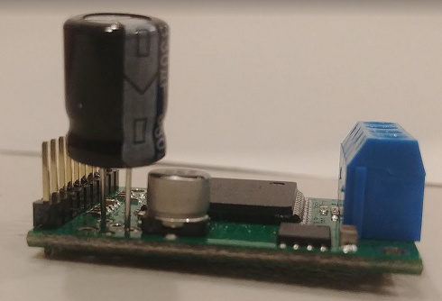
My local Pololu reseller didn’t have your capacitor in stock so I bought a 330uF 25V capacitor from the local electronics store instead. I see what you mean about vertical space, as the additional capacitor looks like it needs to sit above the built-in capacitor. I assume that the capacitors shouldn’t touch each other.
I haven’t soldered it yet, just wanted to get your thoughts on the placement.
How would I go about testing that I’ve soldered it the right way around? Is just connecting power to VIN and GND sufficient, or do I need a PWM signal and a motor as well?
The way you have your capacitor lined up in your picture is correct. (For reference, the stripe on the body indicates the cathode lead, which should be connected to ground.) If you solder it on backwards it will break when you apply power, or it could possibly explode and damage other components, so don’t do that.
I soldered the additional capacitor onto both boards and connected power via VIN. I left it for a minute and nothing exploded. I measured 12V across the capacitor with my multimeter. I’m calling this a success - thanks for your help!