This is my first time working with PWM and motor drivers, so this may be a very simple problem…
I am using the VNH3SP30 to drive a DC motor. I am putting in a supply Voltage of Vcc = 15V. To get a clockwise rotation, I am following the normal operation truth table, with:
INa = 1
INb = 0
ENa = 1
ENb = 1
I am have a PWM signal of 5V coming from a microcontroller. I am measuring the output Voltage across terminals OUTa and OUTb. Unfortunately, this is only on the order of millivolts. I should be expecting 7.5V since my input has a duty cycle of 50%.
Does it sound like I have the right connections for this operation?
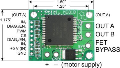
It sounds like you’re using the VNH3SP30 carrier board, is this correct?
When you say your Vcc=15V, I hope you mean you’re applying 15V and ground to the two big sockets on the bottom of the image labeled VIN and GND, right? You also need to connect 5V (and no more!) and ground to the pins on the lower left labeled +5V and GND.
INA and INB control the direction/mode of motion, so you’re selecting clockwise rotation (by the datasheet convention, of course it depends on how you wire up your motor). ENA and ENB are actually pulled high by resistors built into the carrier board, so they’re basically acting as diagnostic pins you can monitor to detect fault conditions. You’re not hurting anything by pulling them high, but you can also just leave them disconnected. I’m not sure which pin you were using for this, but you want to connect the PWM signal form your microcontroller to the input pin labeled PWM, and the microcontroller and motor controller must also share a common ground.
Also, in general you need a path for some current to flow for the transistors in your H-Bridge to operate properly (I always forget this, and think my motor driver isn’t working for a couple of minutes). It doesn’t have to be much current, try putting a 1Kohm or so resistor between the motor outputs and measuring the voltage drop across it. Also, unless you have a fancy RMS voltmeter, you generally can’t expect good measurements of high frequency PWMed voltages. I would expect you to see more than a few millivolts though, especially at higher duty cycles, but you could also try putting an LED+resistor or a motor there to have a sure indication of when the juice is flowing.
I’m actually just using the VNH2SP30 chip. I’m applying the 15V supply to Pin #3 (Vcc). I have the PWM signal from the microcontroller going to the PWM input on the chip. I’ve attempted putting the output across a 10K resistor, and then I tried across my motor, but so far I have not seen any results.
In terms of measurements, I am checking the output with both a multimeter and an oscilloscope, so I am able to view waveforms.
Since I am using only the chip, maybe I need resistors at my inputs?
Aah, in that case you do need to pull ENa and ENb high with either resistors or pins on your microcontroller, like you were already doing. It’s a good idea to put current limiting resistors (1Kohm would be fine) in line with your signal lines, but they’re not 100% necessary if you’re just connecting them to TTL level digital output pins on your microcontroller. With a resistor across the motor outputs you should totally be able to see the same PWM output on an oscilloscope as you are inputting on the PWM pin (can you verify the input PWM on your scope?).
If you’re just using the bare chip, are you connecting both the GNDA and GNDB pins to ground? They’re not connected internally, and there is no separate digital ground pin, so to be sure you should connect at least one GNDA and one GNDB pin to ground, if not all of them.
Any luck now?
-Adam
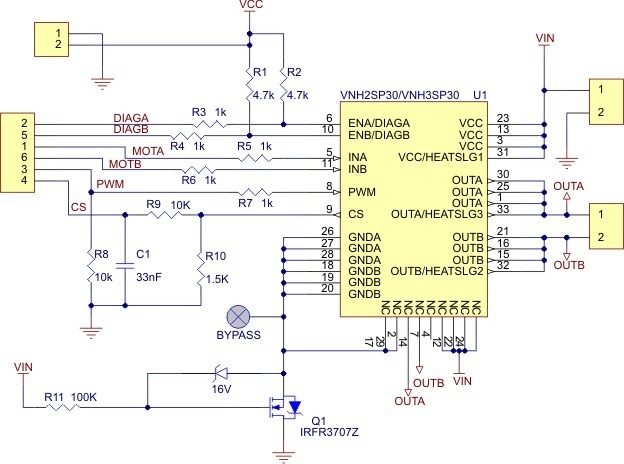
P.S. I’m not sure if you’ve seen this yet or not, but Pololu publishes the schematic for their VNH*SP30 carrier board:
You don’t need to exactly duplicate it, but it’s a good reference.
Thank you for all of your help. I have a couple of these chips, and when I switch them out, two of them show different outputs, so I’m thinking that at least one of them is not functioning properly. Is there an easy functionality test that can be performed?
How are you “switch[ing] the chips out”? In my experience, it’s quite a pain, and it’s conceivable that they could get damaged during desoldering. Are you getting good connections on those big pads under the chip? I don’t know of an easy test without making all of the used connections to the chip.