Hi, I recently bought a Pololu VNH3SP30 Motor Driver for a project I am currently working on. I’d like to control the DC motor I currently have (datasheet mfacomodrills.com/pdfs/Minia … motors.pdf), an MFA como drills re 540/1.
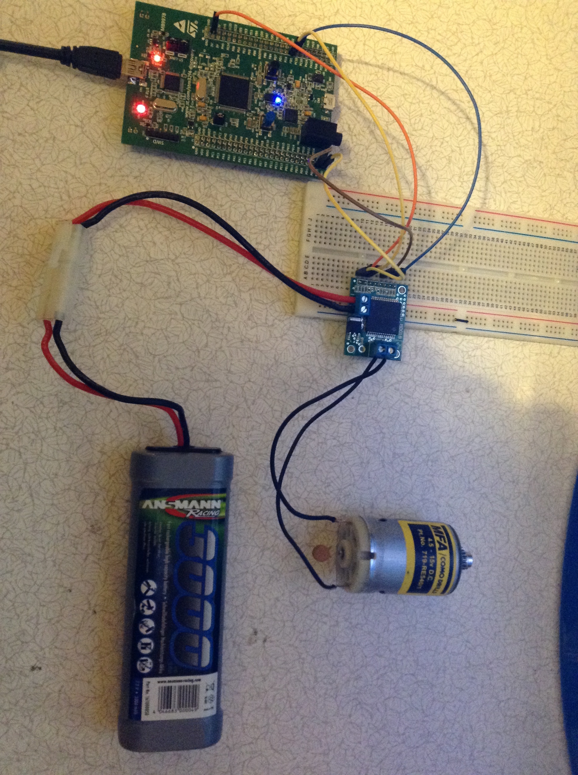
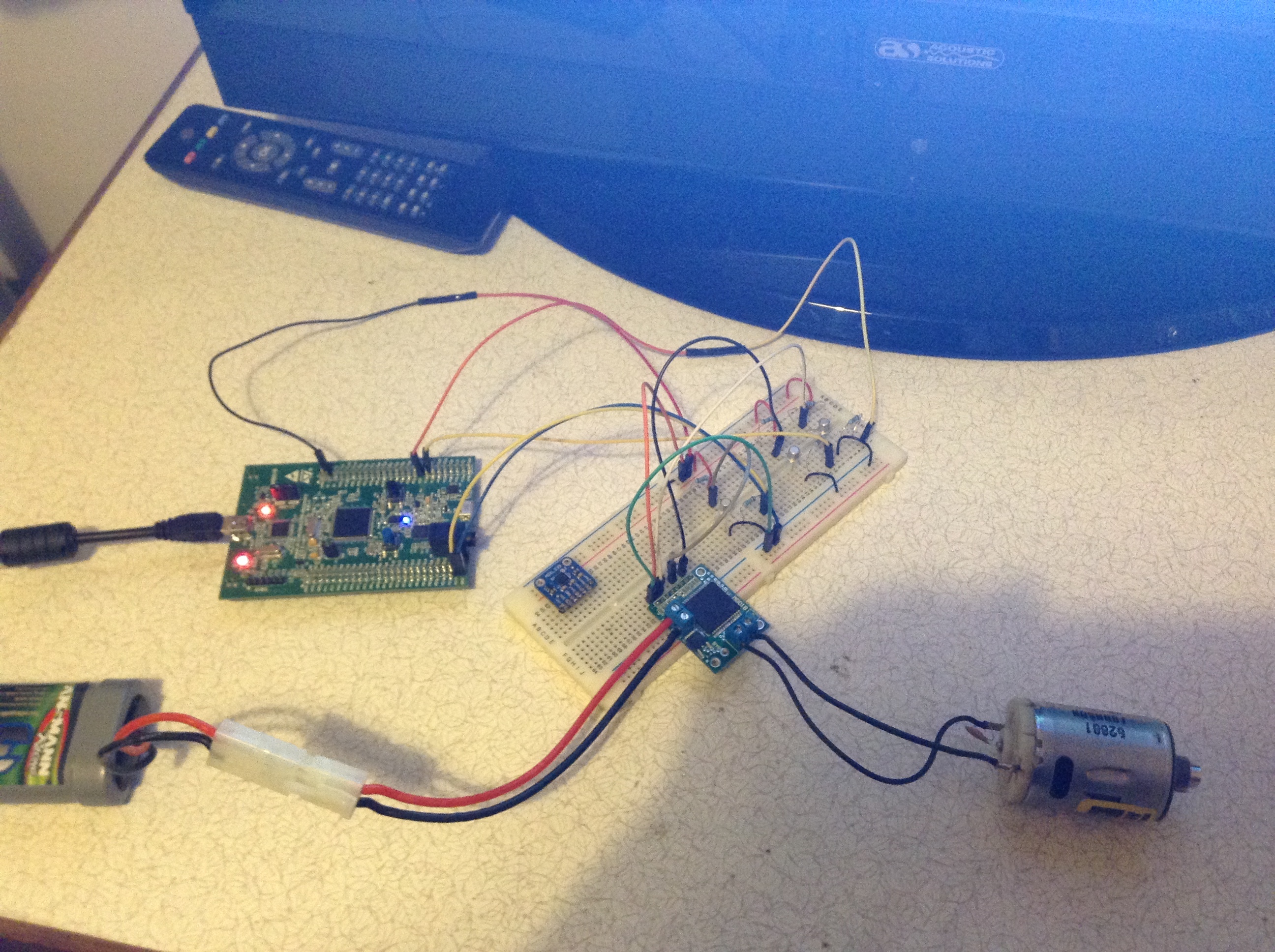
I currently use an STM32F4 Discovery board to produce a PWM pulse of roughly 10kHz at 50% duty cycle (have tried various frequencies 1-10kHz and duty cycles), and to control the state of INA and INB (I will upload a picture of the oscilloscope output on Monday). Unfortunately the motor does not turn when the motor driver is supplied with an Ansmann 7.2V 3000mAh battery supply (datasheet rapidonline.com/pdf/18-3811.pdf). I have tested the input voltage to be 7.4V at the motor driver terminals, also the PWM voltage input is 1.44V at 50% duty cycle and the INA are INB voltages are roughly 2.9V (obv not at the same time :p), but measures 0V at the motor terminals. Attached is a picture of my current setup, where you can see the blue LED which is connected to the PWM timer at 10kHz. Code is below:
#include "stm32f4xx.h"
#include "system_stm32f4xx.h"
#include "stm32f4xx_usart.h"
#include "stdio.h"

void INIT_(void);
//void delay(unsigned int);


/****************************	Main program	*****************************/

int main (void){
	INIT_();
	GPIOD->ODR|=0x01;            	 //Set INA high and INB low for clockwise rotation
	TIM_SetCompare4(TIM4, 250);    // 250 = 50% duty cycle
	while(1){
	}

}

/****************************	Ports and Timer Setup	*****************************/

void INIT_(void){

GPIO_InitTypeDef GPIO_InitStructure;
TIM_TimeBaseInitTypeDef TIM_TimeBaseStructure;
TIM_OCInitTypeDef TIM_OCInitStructure;

/* TIM4 clock enable */
RCC_APB1PeriphClockCmd(RCC_APB1Periph_TIM4, ENABLE);

/* GPIOD clock enable */
RCC_AHB1PeriphClockCmd(RCC_AHB1Periph_GPIOD, ENABLE);

/* INA Port D pin 0 (PD.00) configuration */				                      //INA
GPIO_InitStructure.GPIO_Pin = GPIO_Pin_0;
GPIO_InitStructure.GPIO_Mode = GPIO_Mode_OUT;
GPIO_InitStructure.GPIO_Speed = GPIO_Speed_2MHz;
GPIO_InitStructure.GPIO_OType = GPIO_OType_PP;
GPIO_InitStructure.GPIO_PuPd = GPIO_PuPd_NOPULL;
GPIO_Init(GPIOD, &GPIO_InitStructure);

/* INB Port D pin 1 (PD.01) configuration */			                     		//INB
GPIO_InitStructure.GPIO_Pin = GPIO_Pin_1;
GPIO_InitStructure.GPIO_Mode = GPIO_Mode_OUT;
GPIO_InitStructure.GPIO_Speed = GPIO_Speed_2MHz;
GPIO_InitStructure.GPIO_OType = GPIO_OType_PP;
GPIO_InitStructure.GPIO_PuPd = GPIO_PuPd_NOPULL;
GPIO_Init(GPIOD, &GPIO_InitStructure);

/* TIM4 channel 4 pin (PD.15) configuration */						      //Motor Timer
GPIO_InitStructure.GPIO_Pin = GPIO_Pin_15;
GPIO_InitStructure.GPIO_Mode = GPIO_Mode_AF;
GPIO_InitStructure.GPIO_Speed = GPIO_Speed_2MHz;
GPIO_InitStructure.GPIO_OType = GPIO_OType_PP;
GPIO_InitStructure.GPIO_PuPd = GPIO_PuPd_NOPULL;
GPIO_Init(GPIOD, &GPIO_InitStructure);

GPIO_PinAFConfig(GPIOD, GPIO_PinSource15, GPIO_AF_TIM4);

TIM_TimeBaseStructInit(&TIM_TimeBaseStructure);
TIM_TimeBaseStructure.TIM_Prescaler = 16;					//(sysclk/2/5MHz Timer 3 clk)-1
TIM_TimeBaseStructure.TIM_Period = 499;	                      //(5MHz/10KHz output clk)-1  produces 10kHz output
TIM_TimeBaseStructure.TIM_CounterMode = TIM_CounterMode_Up;
TIM_TimeBaseInit(TIM4 , &TIM_TimeBaseStructure);

TIM_OCStructInit (& TIM_OCInitStructure);																	//Setup Output Capture Compare
TIM_OCInitStructure.TIM_OCMode = TIM_OCMode_PWM1;
TIM_OCInitStructure.TIM_OutputState = TIM_OutputState_Enable;
TIM_OC4Init(TIM4 , &TIM_OCInitStructure);


// Enable Timer Interrupt and Timer
//TIM_ITConfig(TIM4, TIM_IT_Update, ENABLE);
TIM_Cmd(TIM4 , ENABLE);
}
Please could someone help me to get this working as it’s a crucial part of my project? Thank you ![]()
P.S. If any more info is required please let me know