I am using a VNH2SP30 to drive a 19:1 Metal Gearmotor with 64 CPR Encoder. The input voltage to the driver is 12V from a wall-wart voltage adapter capable of 5A (motor’s stall current).
The input PWM (range 0-255 for 0-100% duty cycle) is being generated by an Arduino Mega and this signal is correctly being produced.
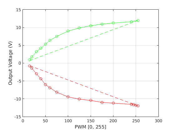
However, the output voltage of the driver (measured by a multimeter) seems to be a nonlinear function of the input PWM as shown in the graph below.
The colors green/red correspond to the two directions of the motor, and the dotted lines show the theoretically correct response.
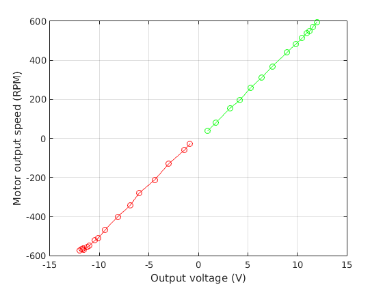
The output voltages that I measured using the multimeter are correct, since the no-load motor RPM reacts linearly to these voltages, as shown in the figure below:
I measured the RPM from the encoders on the motor sampled by an Arduino sketch.
So, my question is what is causing this nonlinear PWM to output voltage relationship? I expected that if I reduced the PWM from 255(100%) to 127(about 50%), the output voltage will also be halved. But this is not so. I tried several different drivers but they all have similar curves.
Any ideas how this can be fixed?
The behavior you are seeing matches what we would expect from the VNH2SP30 driver. In drive-coast mode, during the off-portion of the PWM cycle, the inductance of the motor creates a back EMF, which pushes against the current and maintains the voltage across the motor terminals.
You might see slightly more linear results when under load. If this does not work for your application, you might try compensating for it in your Arduino code. Alternatively, you might consider a different driver that can operate in drive-brake mode, such as our High-Power Motor Drivers.
Thanks for your reply - it certainly sounds plausible.
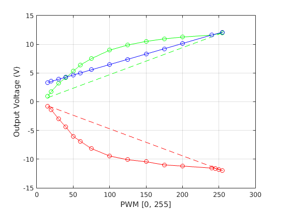
To test this hypothesis, I disconnected the motor and then measured the output again.
The result is shown below by the blue line
So, the non-linearity is certainly due to the motor. However, I am still puzzled why the blue-line is not the same as the dashed green (theoretically correct) line. Any ideas?
I will compensate for this effect in the code - I just wanted to make sure that I am not making any obvious mistakes.
If the driver were operating in drive-brake, the output would better match the theoretical data you are comparing it to. However, since it uses drive-coast, one of the outputs is at high-impedance during the off portion of the PWM while the other is held high the whole time. Are you using the Dual VNH2SP30 Motor Driver Carrier? If so, the motor indicator LED circuit on that board is partially pulling the voltage back up during this off time, which is probably what you are seeing in your measured data.