VNH2SP current sense problem

Hello All,

I am using a VNH2SP, and I made a pid controller using a tiva-c microcontroller board from texas instruments.

I also made a routine, that reads the voltage from CS pins of the dual motor carrier, average them, and plot amongst measured rpm vs applied pwm input, for both motors.

There is a small problem however, the CS_B output influences the CS_A. if CS_B rises above 0, CS_A will read 15-16 (16 / 1024 on a 3.3V scale) if CS_A rises above 0, it has no effect on CS_B.

I took a screenshot to illustrate the problem:


on the bottom of the screen, there is the motor a part. as seen input is given which leads to rpm, and output on a. (green and blue) - as seen, the red (CS_A) increases as well, and after the setpoint is set to 0, it will converge to zero along with the rpm and pwm - as expected.

I then apply a positive setpoint on the motor_b. (the above part of the screen - please notice that the time axis is reverse of what you would expect from a scope) the rpm, pwm and current rise, but notice how the red line on the bottom of the screen also rises a little bit. (it will not change relative to the CS_B but just sit there)

Also characteristics of CS_A and CS_B are different. It seems I get a %20 more reading from CS_B. All those are tested with currents under < 1A.

It seems like a little nuisance, and I could put a bias filter, on the CS pins, and go from there. But I want to figure out why this happens. Since it is a dual carrier board and has 2 VNH2SP’s on it, I dont think it is a chip problem. It could be related to the wiring of the polulu board, faulty component, or my measurement fault in general. I am planning to use the CS as a way to cut power to the motors, then the current increases above a threshold.

Any ideas/recomendations/help greatly appreciated.

Thanks,
C.

Hello.

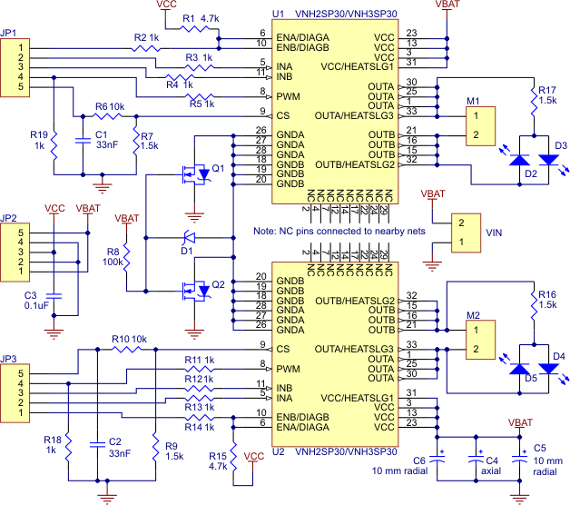
The circuitry for the current sensing for the two IC’s on the board is separated, as you can see in the schematic for the board.

It sounds like you have a pretty complicated setup to take these readings. You might try disconnecting everything from the board and testing the CS pins with a multimeter to measure the voltage to see if the cross-talk is still there.

By the way, the accuracy of the current sensing on these chips is limited, so if you want accurate measurements at low current, you will likely need to perform a calibration with a more accurate instrument. Also, the sensing circuitry within the IC is different for different rotation directions, so the calibration parameters could be different for running the motors in forward and reverse. If you want to know more about why this is the case, you might want to look at these two forum threads here and here.

-Nathan

Hello Nathan,

There is definitively some cross talk between the current sense outputs, regarding left and right motor.

I also discovered that, setting one of the motors in brake will reset the residual charge at the CS pins.
I believe what happens is that the capacitor that filters the output keeps some of the charge.

I also have been able to observe that characteristics of reverse and forward current sense is a little different.

I think it could be fixed with some filtering, but anyhow I will just use the CS output for stall detection, so not big deal.

Best regards,
C.

OK. If you change your mind and decide you want to troubleshoot the cross-talk further, let us know. It is possible that the cross-talk could be occurring in the ADC of the microcontroller you are using or some other portion of the circuit, so simplifying the circuit to find the source of the cross-talk is the best way to proceed with that.

-Nathan