
Hi,
I just bought the VL6180X Time-of-Flight Distance Sensor Carrier with Voltage Regulator for a short-distance measuring task, but having some trouble get it working.
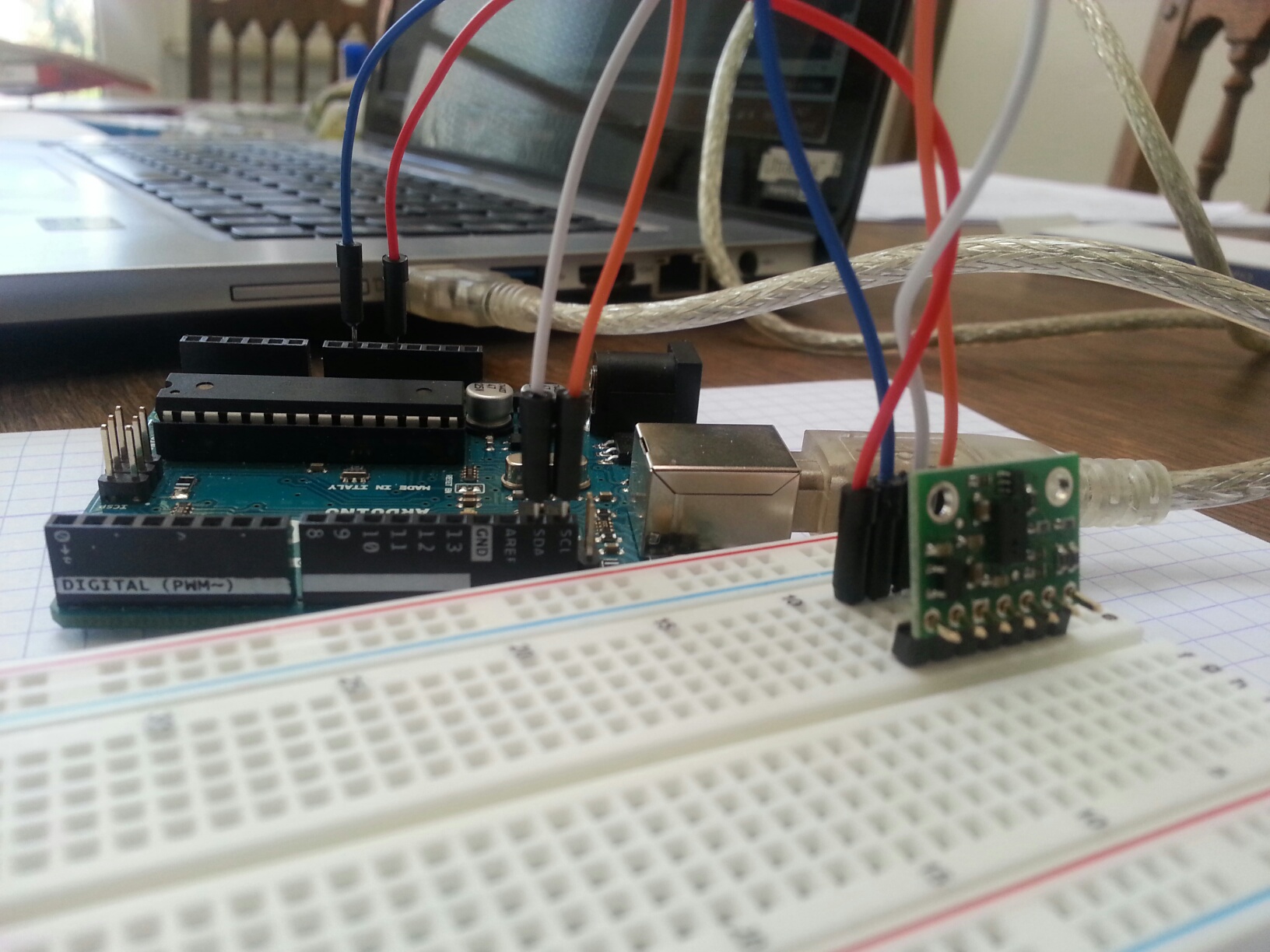
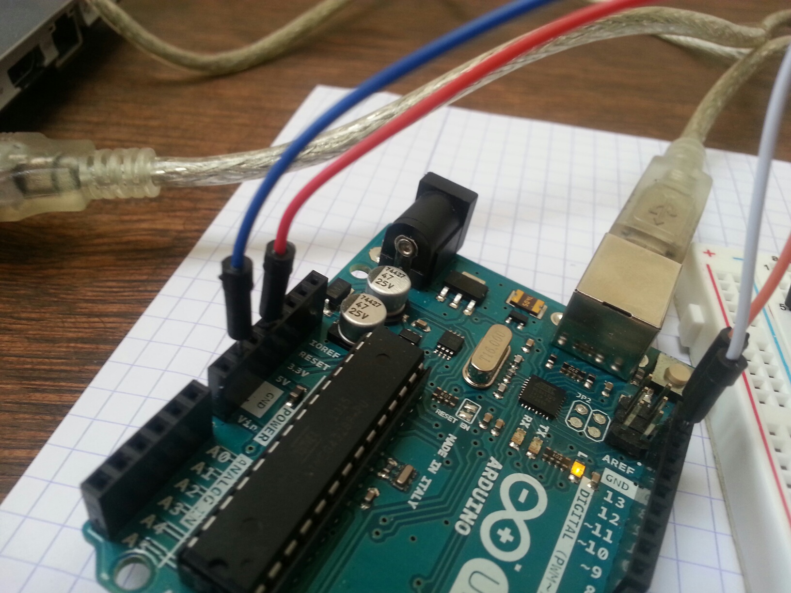
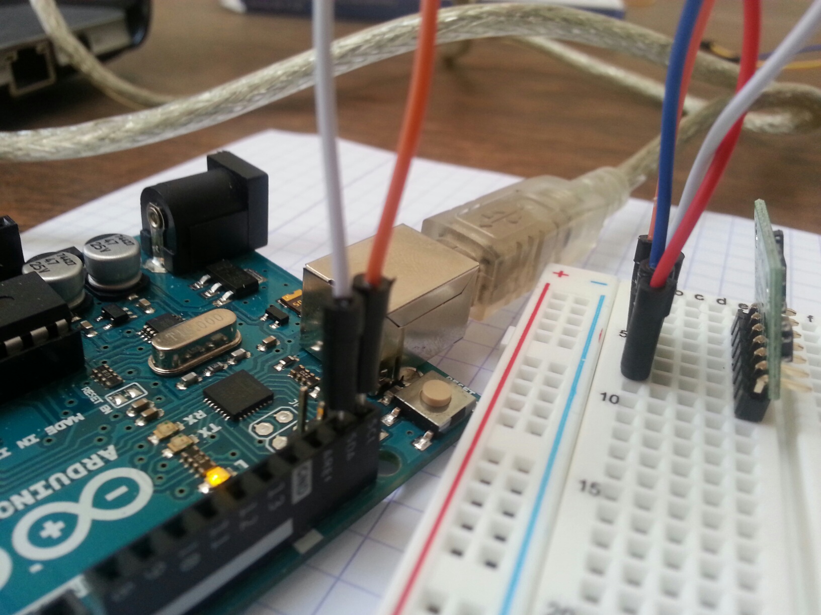
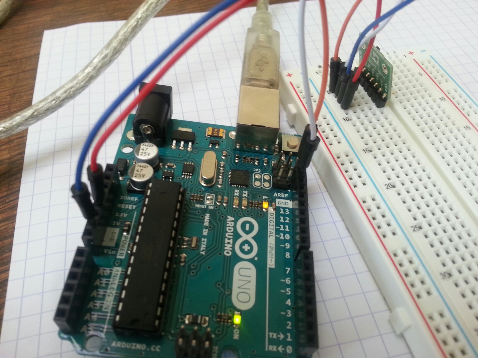
Wired accordingly Vin->5V, GND->GND, SCL->A5, SDA->A4 with an Arduino Uno R3 Board (IDE 1.68), loaded the Sample Codes and gave it a run.
There is output on Serial Monitor, but showing only constant values, on all three examples sketches.
I tried the Arduino I2C-Scanner to check if the Sensor is being recognized on the bus, but was not!
I tried a different I2C-Sensor (DHT31-D) which I use in this project, being recognized by the I2C-Scanner on (0x44). As this one works fine, I think, there could be an I2C communication problem on the VL6180X.
I then checked voltages to see if there might be issues with level-shifting.
SDA/SCL=VIN, VDD/GPIO1 =2.78, this looks fine.
But: Voltage on GPIO0 = 0!? Shouldn’t this have been pulled up to VDD to enable the sensor at startup?
Any ideas?
Rgds, Steve
Hello, Steve.
I am sorry you are having trouble using that sensor. The board is designed such that GPIO0/CE is pulled-up to VDD, so it should not measure 0V when powered unless there is a short to ground (or it has been reconfigured as a programmable interrupt output). What are you using for 5V and how much current can it provide? Can you post pictures that clearly show your soldering joints and connections?
-Jon
Hi Jon,
many thanks for your reply. Today I followed your recommendations (double, triple checked all connections, solderings, volatage supply etc.) I could not find any issues with that.
Finally I found out, that the problem was related with my COM Port communication, being very sensitive and unstable for whatever reason. (I need to further investigate on that.) My bad! Sensor works as expected, providing readings on all three sample sketches on the go.
Rgds, Steve
I am glad your sensor is working now; thanks for letting us know what the issue was!
-Jon
i have the exact same problem described by Steven_S, same sensor, same board and IDE 1.6.8
i have always a read of 255 (end of scale)
the soldering and links are ok (seems good)
i use the official library and example sketches from Polulu
VIN = 5V
i see that the data coming from serial are quiet strange…the stream is not constant in time…sometimes
i have data every 500 ms…sometimes every 2 seconds without changing anything on sketch
i have tried with Arduino 101 but without luck
the library send 255 value even if there is no sensor attached to board
i cant confirm Steven_S
2.77 V on VDD
2.65 V in GP01
but i have 2.65 V in GPIO0
looking with I2C scanner i can’t find any device
any suggestions???
is dead on arrival ??
thanks
Luca
ok i have rechecked all and now works fine (i think was a problem on SDA solder)
thanks
L
Hello, Luca.
I am glad things are working; thanks for letting us know what the issue was.
-Jon
I’m having a similar issue with the VL6180X connected to an Arduino Uno. When I run the “RangeSingleShot” program, I get a constant reading (255) in the serial monitor - same for the other two sample programs.
I’ve tried replacing the wires, ussing a different sensor of the same model, and changing the position on the breadboard. I also put the sensor flat on the breadboard and used the wires to directly connect it to the breadboard (not shown in pictures) - it didn’t change anything either.
The baudrate in the code (9600 baud) is the same is in the serial monitor. Sample code in the Arduino library works just fine, so it doesn’t seem to be a problem with the Arduino. I’m using the Arduino IDE 1.8.5.
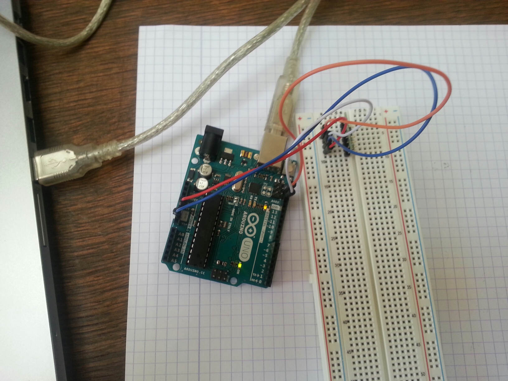
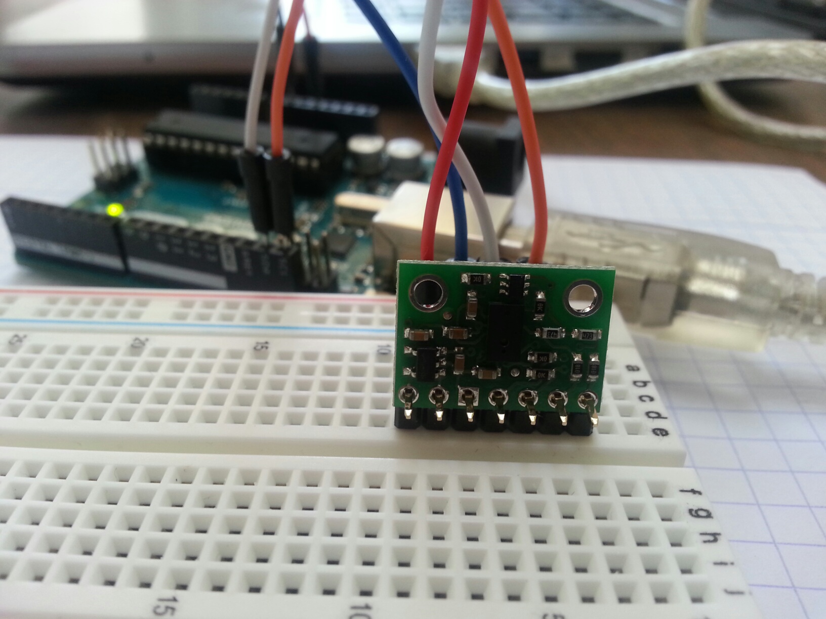
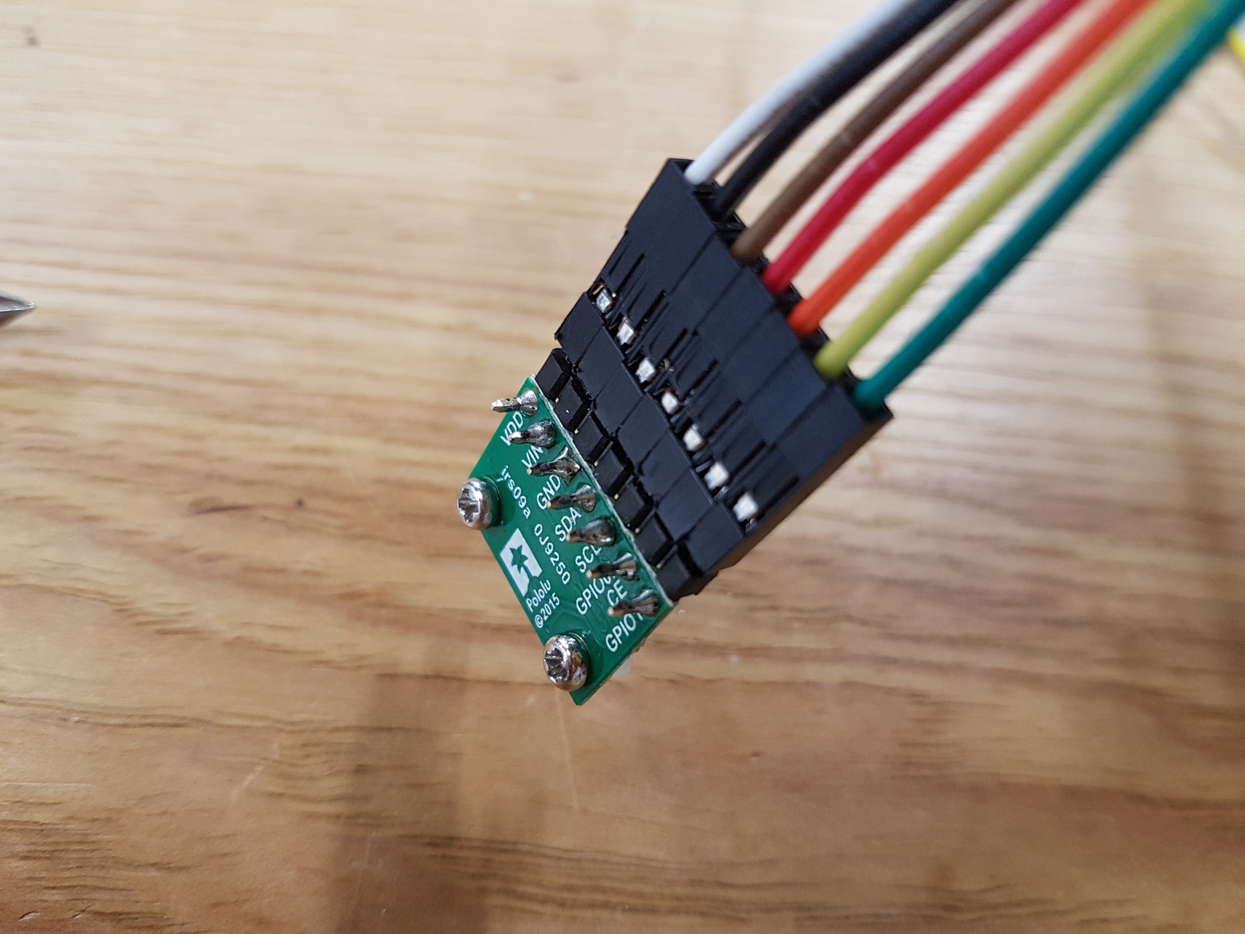
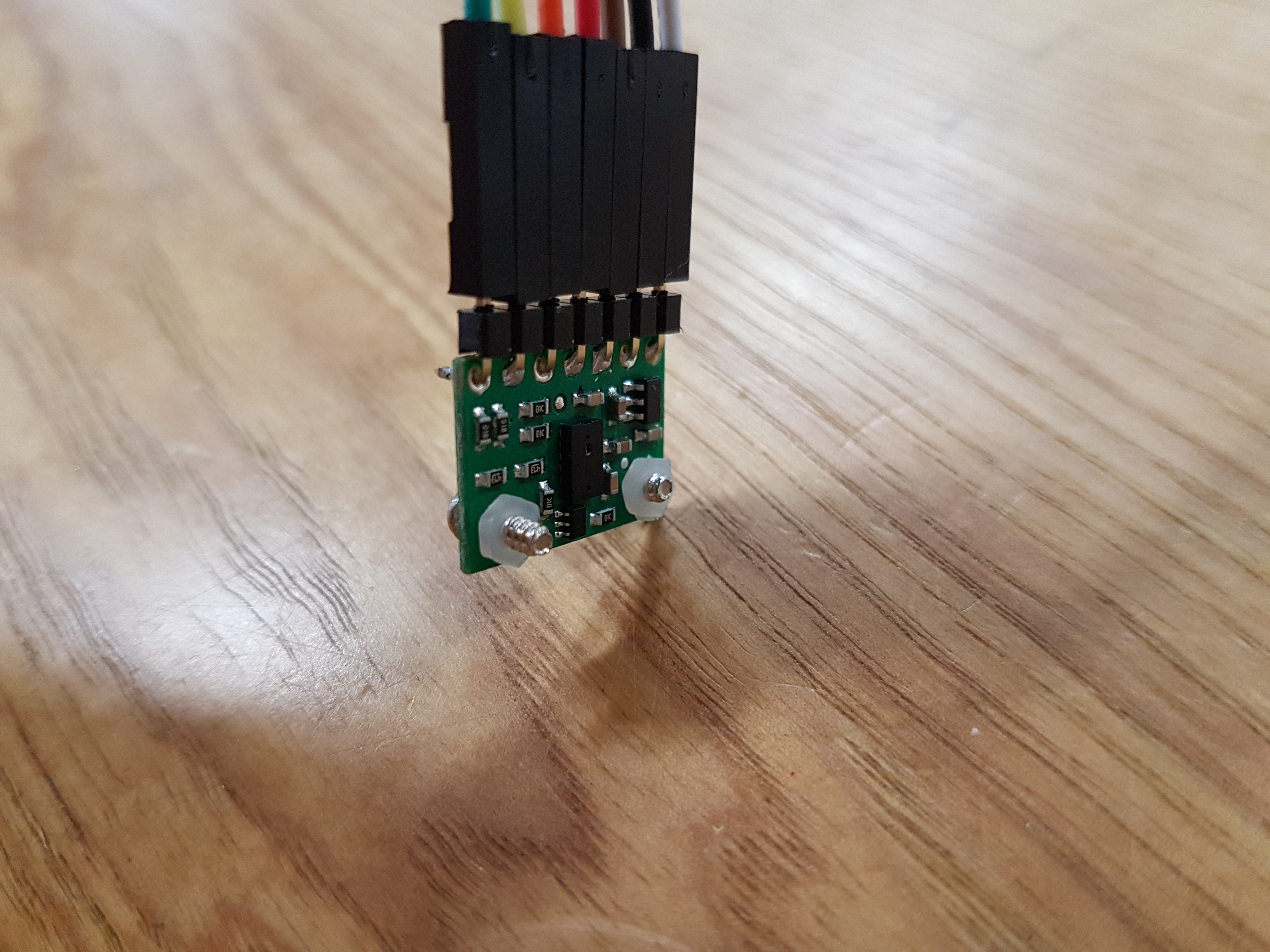
I’ve attached pictures of the setup (all the same setup). I’m sure there’s something simple I’m missing.

Thanks,
Sabine
And I should add - I made the same connections described on the Github website for the VL6180X library for Arduino:
Arduino VL6180X board
 5V - VIN
GND - GND
SDA - SDA
SCL - SCLHello.
It looks like your board is not soldered. Can you solder your connections and try again? In case it helps, you can refer to this Adafruit guide to soldering, which also has pictures of what an ideal soldered joint should look like.
-Jon
Yes, this did the trick. Thanks Jon!
Hi, I’m having an issue similar to skunz, where the output is constantly 255. I’ve tested all the connections (from the pin plugged into the arduino to the soldered pin on the VL6180X board itself) with a voltmeter, and they all seem to be connected and work, and I’ve tried using both the 3.3V output and 5V output, but it didn’t seem to work both times. I’ve also tried this with an Arduino Uno and Due, which both don’t seem to work. Any suggestions would be appreciated.
Hello, 19minersr.
Can you confirm that you were also running the “RangeSingleShot” sketch from our Arduino library for the VL6180X, and can you post pictures that clearly show your connections and soldered joints?
-Jon
Yes, the values are reported as 255 for both the RangeSingleShot sample sketch and my modified sketch. I’ve tested the connections with a voltmeter so they should be fine. Here are pictures of my setup, it is usually plugged into a 5v wall adapter as well. (The crossed out wires in the last picture are for something else.)
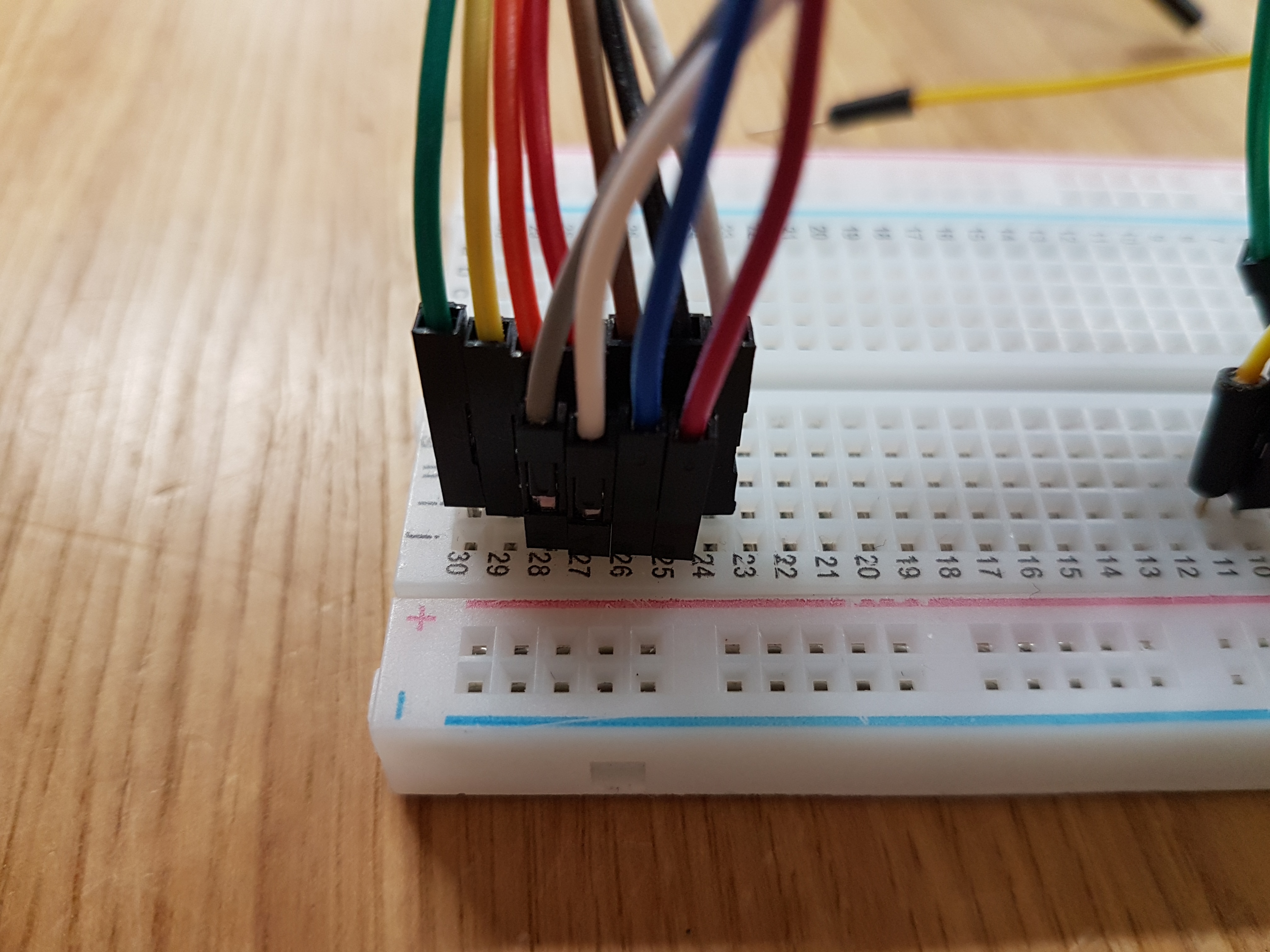

Hello.
First, you should remove 5V from VIN on your VL6180X and instead supply 3.3V from your Due. This is because the Due is a 3.3V device (and its GPIO pins are not 5V tolerant), and supplying 5V to VIN on our VL6180X carrier board causes the I²C pins, SDA and SCL, to be pulled up to 5V, which could damage the pins on your Due.
Then, can you try using pins 20 (SDA) and 21 (SCL) instead of SDA1 and SCL1? We expect that to work as-is when running the RangeSingleShot sketch unmodified.
-Jon
I switched from 5V to 3.3V and to pin 20 and 21, and it now works. Thank you!
Hey guys, I have the same problem and tryed every solution but can’t get it to work.
I use an Arduino Uno R3 and everything is connected as described, but if I run the RangeSingleShot it only gives me a 255 loop.
Am I missing anything?
Checked the soldering and tested with a voltmeter and it should have power.
Or could the sensor be damaged?
Hi, mrvnttt.
Could you post some pictures of your setup showing how you have everything connected?
Kevin