


Hi, I am trying to use SPI with the VL53L8CX but i just cant get it to work. I2C is working fine but SPI not at all. I read at the ST-Forum about a faulty level shifter… Solved: VL53L8CX SPI doesn't work properly - STMicroelectronics Community.
Any help is welcome.
Thanks!
Hello.
We test these the SPI communication on every unit, so the board itself is probably okay (or at least, it was probably okay at some point). However, as we note on the VL53L8CX carrier product page, the level shifter on this board is more sensitive to external loads than the circuit we typically use, so we recommend taking extra care to keep connected communication wires short (ideally under 3 inches or 8 cm) and limit other devices on the same I²C or SPI bus.
Can you provide more details about how you are trying to use the VL53L8CX (microcontroller, power supply, etc.) and post some pictures of your setup that show all of your connections? Also, can you look at the SPI signals with an oscilloscope and post captures of what you find?
- Patrick
I support the ST VL53 ToF products, and I know what is wrong.
The NXS0104 you used will not do the job - with ST’s Nucleo boards anyway.
We at ST had the same issue.
If you swap that part for a PI4ULS3204 it will work.
(Our supplier thought they were equivalent, but they are not.)
Hi, John.
We have tested our VL53L8CX carrier with SPI on several controllers and confirmed that it works, including with an ST Nucleo-F411RE running the CubeIDE_F401RE_Example_SPI code from the ULD API:
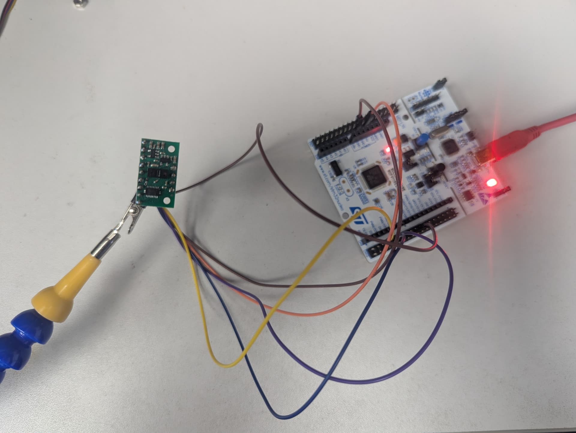
Our carrier board is intended to let people use the sensor with 3.3V and 5V controllers, and it was never intended to work at lower voltages. (The PI4ULS3V204 doesn’t seem to go up to 5V, and it’s not available in an 8-channel version, which is why we chose the NXS0108.)
Kevin
2 Likes
I tried it as well, with 4 pieces, none worked on SPI. Tried on ESP32, ESP32 S3 and P4 Nano boards.
I put together 4 of this sensor (pololu module) on one ESP32 P4 Nano board and after plenty of tweaking got them all working in I2C with full sync.
Any idea when the STEVAL-VL53L9 module be available?
Hello.
As mentioned earlier in the thread, we test these the SPI communication on every unit, but the level shifter on our VL53L8CX carrier is sensitive to external loads. If you post more details about how you are trying to use the VL53L8CX (microcontroller, power supply, etc.) and some pictures of your setup that show all of your connections, then I might be able to offer some suggestions to try and help. Can you also look at the SPI signals with an oscilloscope and post captures of what you find so we can see what is going on?
From ST’s website it seems like the STEVAL-VL53L9 is not released yet, and the sensor it is based on, the VL53L9CX, is still being evaluated. We do not have any additional information about when to expect those to become available; you might try contacting ST about that directly.
- Patrick
1 Like
Hi Patrick, thanks for the response 
I use 4xVL53L8CX on a esp32 board with 2x i2c channels - works all the time. For both 10 & 20 cm (F/F) DuPont jumper cable. For SDA and SCL cable common per 2 sensors. 1x Sync for all 4 and 1x INT per sensor.
Same board, same 10cm cable on SPI, I get no response or signal whatsoever on the serial monitor on the arduino ide, even for single sensor. I saw that you (I mean datasheet) recommend cables shorter than 8 cm but those may not be suitable to me as of now (maybe later on with custom pcb) and its pretty tight space with 10cm cable connecting all 4 to the board.
To give u an idea of my setup, i placed 4 sensor as a cluster grid 2x2 together so that I can get more detailed resolution of the object. I use the INT and SYNC pin to get a sync 16X16 data and with 2xI2C I get ~13 fps, I want to increase it further with SPI if possible. But a ETH drone paper (with 12 sensors) said they used two SN74LVC125A chips per side of the connection. Is there any other way?
Is there any 16x16 version of this sensor in the making or alternative?
Thanks
@Drpk SPI is much less forgiving than I²C over jumper wires. Your I²C results suggest the sensors are working correctly. The SPI wiring is likely causing signal integrity problems. Ten-centimeter Dupont wires can already affect SPI reliability.
Try reducing the SPI clock to 1–2 MHz first. That often improves communication without hardware changes. The SN74LVC125A buffers improve signal quality, not protocol compatibility. They help drive longer connections and multiple sensor loads. Good grounding and shorter signal paths are equally important. For a permanent design, consider reliable wire to board connectors instead of Dupont jumpers, as they provide a more robust interconnect for multi-sensor assemblies and custom PCBs.
Hi @ justbeatit
I tried it from 100 khz to 4 mhz and no response at all so I need to change the connection type itself fundamentally. Will the SPI mode work for my setup if I manage to shorten the cable length? Any specific wire to board connector recommendations? I use ESP32P4 Nano board and STM32F407 Disc board.
I also have some questions regarding this sensor which I have posted in that product page, pls clarify those as well if u can.
Thanks.
If you redesign the wiring with shorter cables, a solid ground return, and a cleaner layout, SPI should be able to work on an ESP32-P4 Nano. Many developers run SPI successfully with the VL53L8CX. They typically use short PCB traces or compact cable assemblies instead of loose Dupont jumpers.
ST’s UM3109 user manual (which you can find on our VL53L8CX carrier product page under the “Resources” tab) indicates that the maximum ranging frequency for the 8x8 multizone mode is 15 Hz, so if you are already getting around 13, then it seems like you are already pretty close to the maximum possible. Unfortunately, I do not have any specific suggestions for getting closer to that maximum.
Other than the VL53L9CX that we discussed earlier in the thread, it does not seem like ST has any other time-of-flight sensors with greater multizone detection capabilities, nor do we have any additional information about what might be in the works.
It seems like there might be a lot going on in your system, so for issues like these that makes it difficult to predict with confidence what or will or will not work in your particular setup. @kevin posted a picture earlier in the thread of a setup where SPI does work, so if you are motivated to try to get SPI working, then I recommend you start by building a simplified setup similar to that first and see if that works. If it does not, post some pictures here and we can try to help you get it working. If it does work, then add features from the rest of your system one at a time to see when you start having problems. Whenever you test changes to your setup, monitor the signals with an oscilloscope so you can see how those changes affect the signal integrity.
I replied to your comment on the VL53L8CX new product blog post.
- Patrick