
Help required to make SPI work with 3 VL53L8CX modules

Hello,

I bought 3 of your VL53L8CX modules and would like to make them communicate using SPI with an ESP32S3 ETH board.

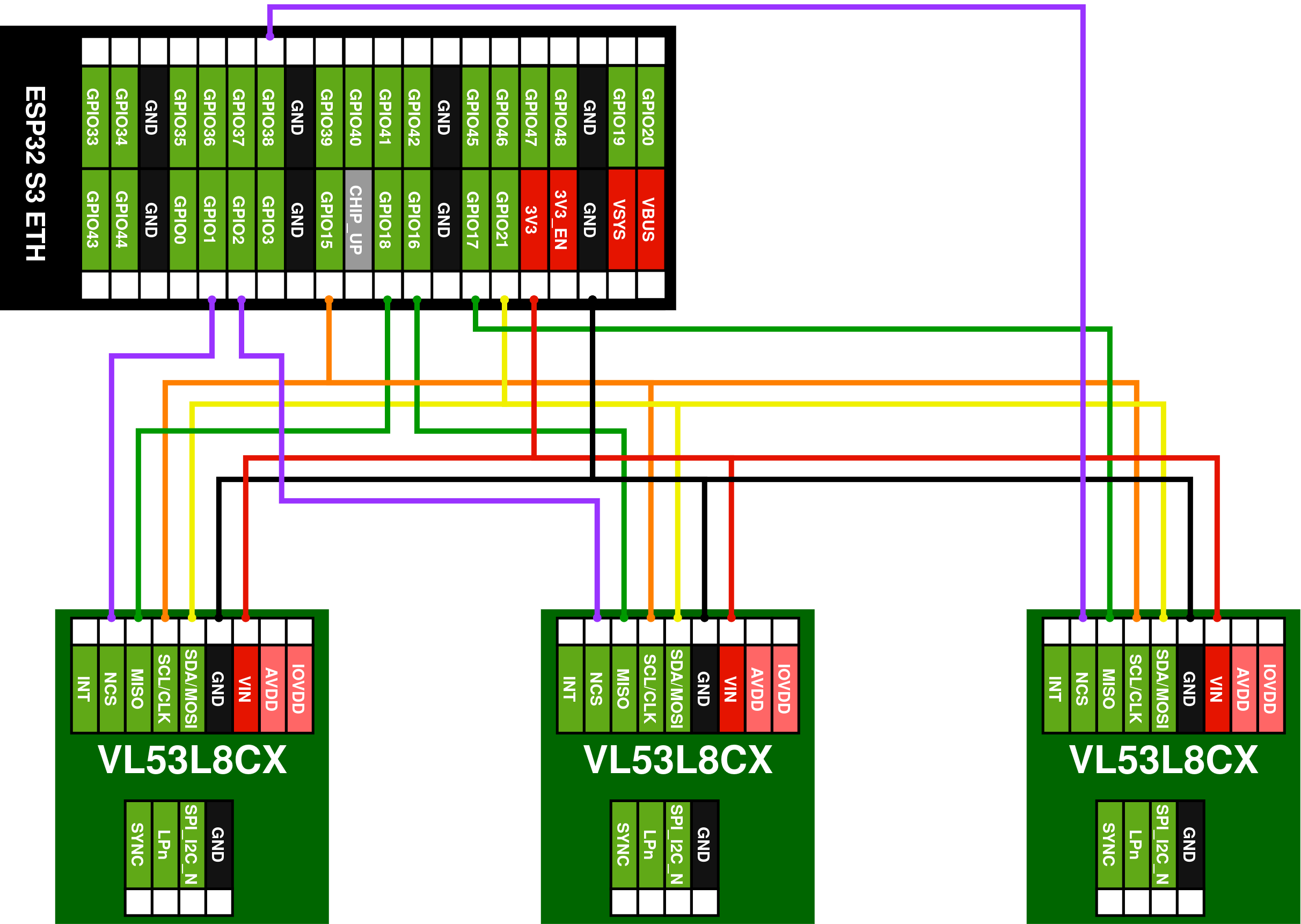
My wiring is:

  • MOSI → GPIO18
  • CLK → GPIO15
  • MISO → GPIO3
  • CS1 → GPIO1
  • CS2 → GPIO16
  • CS3 → GPIO17

Here is a drawing that summarize this:
I’m trying to test the sensors on a small prototype, so for now everything is plugged on 2 breadboards (one for the ESP32 and another one for the 3 VL53L8CX modules).

When using short cables (around 10 cm, see the image below) it works quite well.
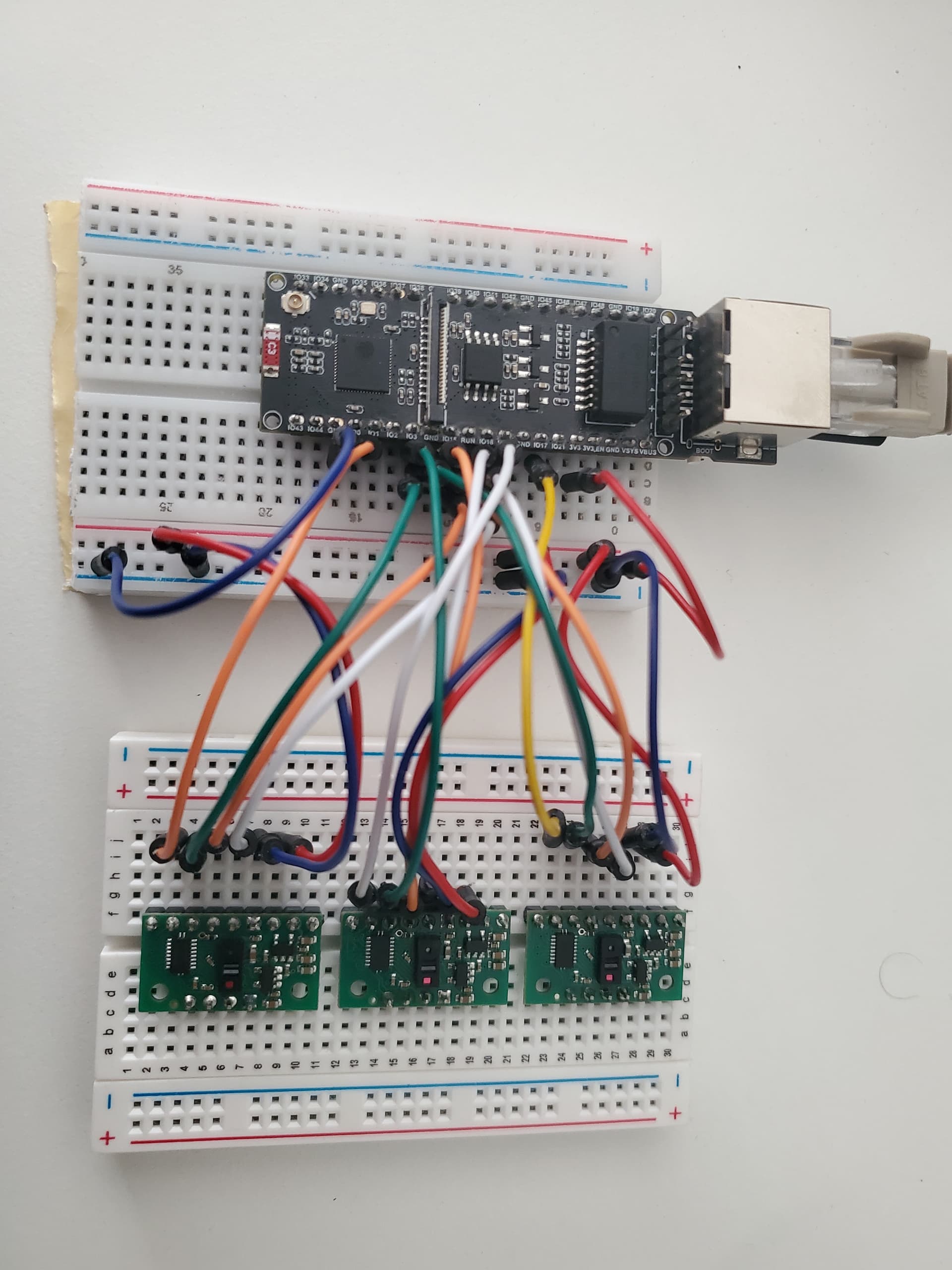
However, with longer cables (around 20 cm), the initialization process fails and the controller is not able to reach any sensor anymore.
If I conduct the same test with only one sensor on the bus, it works fine. With 2 sensors it works 50% of the time and with 3 sensors it doesn’t work at all.

What I noticed is that if I plug my oscilloscope probe on the “MISO” pin of the first sensor, the initialization passes (just for this one sensor though, the other 2 still don’t work). If I unplug it, it fails again. If I plug 2 probes into the “MISO” pins of the first and second sensor then all 3 sensors initiate communication successfully.

Another thing I noticed (but not sure if this is the same issue) is that the CLK signal is interfering with the MISO signal, as you can see here :
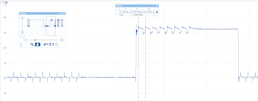
This always happens regardless of the cables length, so I don’t think this is directly related to my main issue but it might have an impact…

I have tried to lower the bus speed from 3 MHz to 1 MHz, without success :frowning:

After a bit of reading on this forum it looks like the level shifters used on the Polulu modules are quite sensitive and using short cables is recommended.

However for my final application I will need to use longer cables, of at least 20 cm. I was considering making a PCB to get rid of the breadboards to improve the connection quality. Do you think this will resolve my issue ?

Also, do you think using ribbon cable (like IDC connectors for example) with alternated GND signals (e.g. GND - SCK - GND - MOSI - GND - MISO - GND - CS) could fix the issue ?

What else should I try to make this work ?

For now, I will try to split the MISO lines on 3 different GPIOs to see if it works better. I am quite inexperienced with SPI communication, any help is appreciated !

Thank you for your time and have a good day,
BR
Its great that you have SPI working for your setup, I use 4x on 2x I2C, 2 per I2C bus and get 13.8 fps on ESP32P4 Nano with 5 features so if SPI is not mandatory then consider I2C. It worked reliably for both 10 and 20 cm cables. I used both the INT and SYNC with the I2C setup and it worked pretty well so I decided to go I2C to avoid trouble with the SPI as it was very sensitive and did not work at all for me.

If SPI is your only option then try the ribbon cable first. There is a research article where they used 12 of this sensor on SPI with ribbon cables but used additional chips to boost the signal quality to address the length sensitivity on this sensor.

Source: https://www.mdpi.com/1424-8220/26/4/1140

Hope it helps.

1 Like

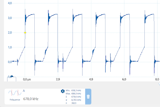
Did you add any additional circuitry to make I2C work ? Like an RC filter or something ? Because when I first tested I2C communication I saw that the SCL signal was really strange and the frequency was way lower then the configured one :

From my understanding of the Polulu modules, it was linked to the bidirectional level shifter that was not switching direction fast enough.
This is (partially) why I switched to SPI, as I thought it would work better with the dedicated MISO and MOSI lines. And it did work better with short cables, so I stick with it (basically the exact opposite of your case :sweat_smile:).

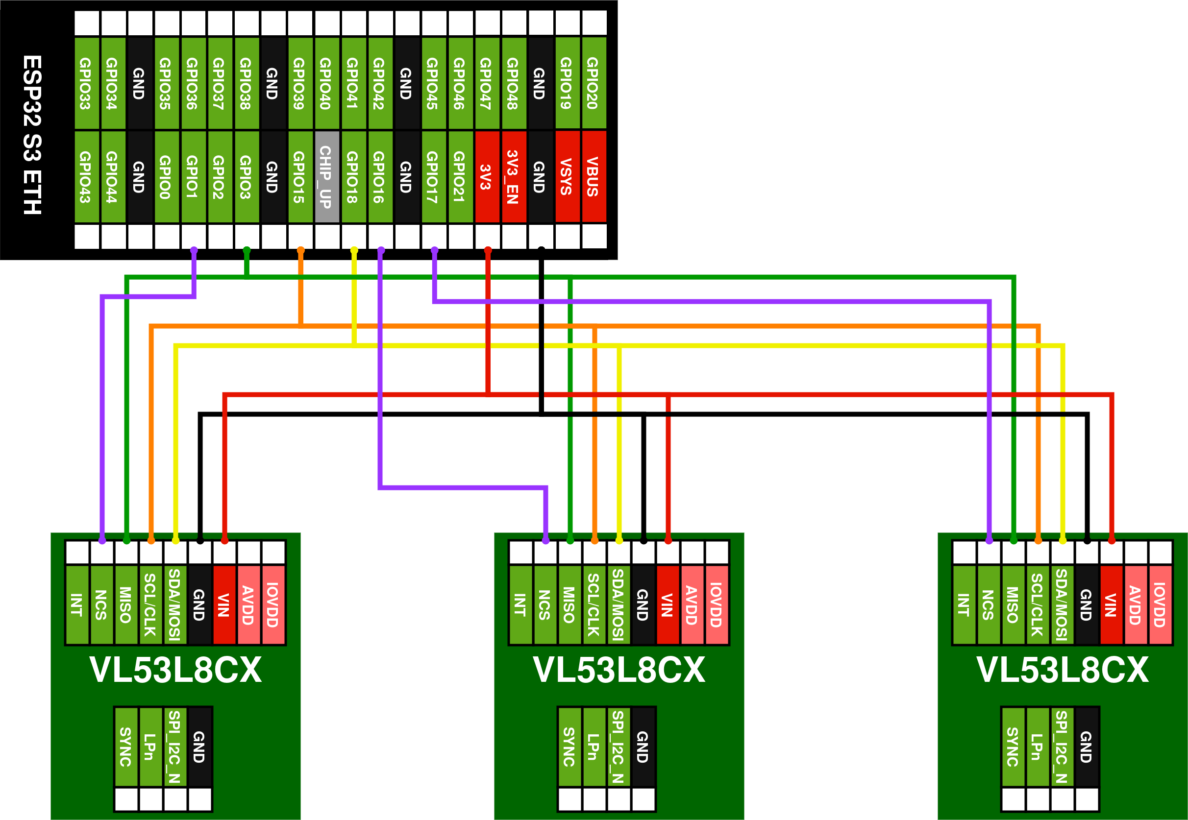
I might give I2C another go, but so far SPI with splitted MISO lines works well. I wired the sensors this way and now I don’t have init issues anymore :

This is a great resource and it helped me a lot, thank you so much for sharing it ! I will try the ribbon cables first and see if I need the additional buffers or not :smiley:

Thank you for your help @Drpk !

1 Like

Hi @paul_m ,

No I used nothing except the Fe to Fe Dupont cables for all the connections and that is the main reason why I decided to stick with I2C. This module is by default on SPI so for it to be on I2C you need to ground the SPI/I2C pin with a jumper plug to the Gnd pin right next to it.

I2C mode has LP pin, which you need to make it go low for all sensors and make them go high one by one to give/assign an address as per the bus lane. Its one time setup code so it will work reliably after that. One quirk I found the hard way is that during this Init phase the I2C bus speed needs to be 100 kHz (for multi sensor), “just for detecting”, and it can then be pumped high to 400khz to 1Mhz during the firmware upload and for ranging. Finding this was the painful part in my entire work.

Good luck tinkering, Cheers

1 Like