USV: Twin 24v23 Drives - No output

Hello, hello.

No output to motors, but the board seems to think it is doing it’s job (no errors).

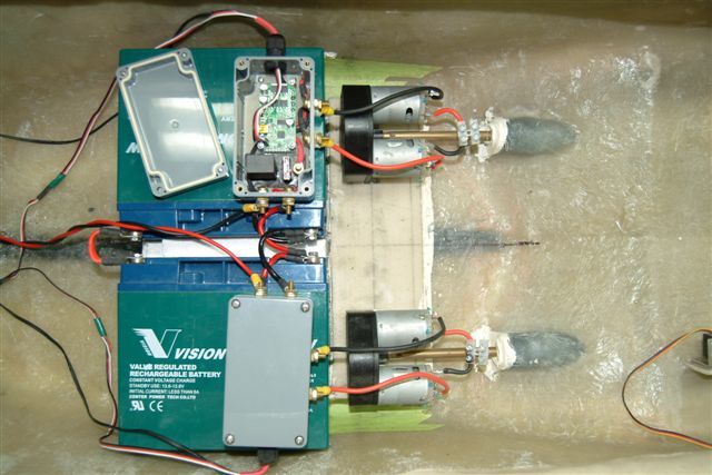
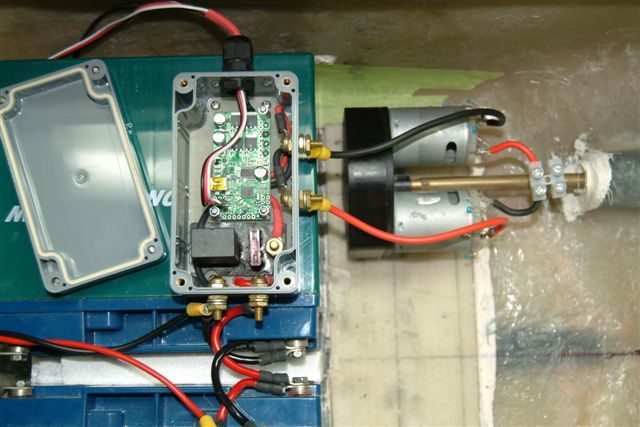
I have two 24V23 Motor Controllers in a boat (USV project) currently running with RC inputs for testing. The two units were previously operating, but now one unit has no output and does not drive the motor.

There are no errors (LED error light, or errors in the control center) but there is also no output to the motor. The second controller continues to operate just fine, with the same shared signal, power supply, etc.

On the non-output controller, it operates as if it is driving the motor, with the staus LED signaling acceleration for an acceleration signal, and no errors present. Viewing the USB Control Center (status tab) the status info shows the motor being driven without errors, but after approx 10 - 20 seconds of showing the Current Speed = Target Speed, the Current Speed drops to zero and the Safe Start Violation error is YES. No other errors are present, and the motor has not been driven throughout.

Meanwhile the second 24V23 controller is operating and has been driving the other motor combination just fine, with no problems. I am using a single common RC signal to both motor controllers.

System description:

  • Boat / USV.
  • Twin propellers.
  • Two 12VDC motors per propeller, connected in series (24VDC motor combination).
  • Motors: 12VDC, No load current 1.0A, Max current 54A, 16500 RPM, this is all I know about them.
  • Two 24V23 Motor Controllers, each unit controlling a 24VDC motor combination of 2 x 12VDC motors connected in series.
  • Power supply: 2 x 12VDC 20AH SLA batteries connected in series (24VDC 20AH SLA).
  • Power supply: Each 24V23 is fitted with a 30A relay & 30A fuse in the power line.

Note 1: Power capacitors supplied with 24V23 are fitted.
Note 2: Power cables (battery terminal to 24V23 board) = approx 150mm long, 3.0mm2.
Note 3: Motor cables (24V23 board to motor terminals) = approx 150mm long, 3.0mm2
Note 4: Hard Limits are set to limit accelerations and inrush current, i.e 500ms delays, no braking.
Note 5: Under full power/load the 24V23 units shut down (overtemp). Water cooler heat sink is to be fitted to mosfets.

So, what is the problem with this non-output 24V23 motor controler that I have here.

Regards,

Jono

Hello, Jono.

Thank you for the thorough description of your system.

Unfortunately, I think that those motors, having a 54A max current, might be too much for this controller to handle. Also, by putting them in series and raising the voltage, you are increasing the chance that there could be some big voltage spike that causes damage.

What do you mean by “no braking”? I would recommend setting the brake duration parameter to something like 1000-2000 ms.

Your non-functioning controller is probably not fixable, but if you email us and refer to this thread, we might be able to at least give you a discount on a replacement unit so you can try again.

–David

Thank you for the reply.

I read the 54A as the stall current, and the fuse is 30A and has not blown. Initial 20A fuses did blow under full load.

The boards have previously shut down when tested at full speed ahead (with the props in the water) but the 30A fuse is still intact when this happens and shutdown is due to overtemp (overtemp setting = full shutdown with full hysteresis). From this I deduce that the full load current of my specific motors/gearbox/propeller system is less than 30A, and probably greater than 23A.

I set the braking to zero, as I did not understand what implications that braking would have on back emf / currents / spikes. Of course, the propellers (and motors) are naturally braked by gearbox inertia and the water resistance on the props. Hard limits are also set to limit deceleration.

The target for the drive system is to fit water cooled heat sinks to the 24V23s and set motor limits to constrain the system to 40A. This meets my approx peak power requirements of 24V x 40A = 960 Watts per drive. I read from other forum comments that this should be achievable with heat sinks.

I take on board your comment about voltage spikes, but do not understand why. I understood that the 24V23 is specifically a 24V controller, and I selected it to operate at 24VDC, i.e. 2 x 12VDC motors in series, to deliver the power required.

Question 1) Are you saying that 2 x 12VDC motors in series are more problematic (for spikes) than a single 24VDC motor? I was only considering LC voltage spikes on VIN (on power switched on, mechanical relay, etc) as the danger area. What are the motor side voltage spike factors that I need to consider/understand?

Question 2) Why are all the control center functions on the board apparently and happily operating normally, with no errors, if there is no output to motors?

Question 3) What more can I do to reduce voltage spikes that may affect this system configuration. I.e. Should I use a fuse in the output / motor side of the circuit?

Question 4) I would prefer a bit more of a specific answer as to why the board may have failed, so as to be able to understand what is occurring. Rather than just ‘try it again’ and get the same outcome.

Many thanks,

Regards,

Jono


Thanks for the pictures.

No, I was just saying that operating at 24V instead of 12V will leave you less margin for over-voltage trouble, but the 24V operation should be fine. Motor-side over voltage problems can arise if a motor goes faster than you can drive it (e.g. a robot rolling down hill); is that possible in your setup?

Not all malfunctions are detectable by the microcontroller. For instance, the chip that controls the MOSFETs could be damaged, as could some of the MOSFETs.

A fuse on the motor side would only help with current problems. I don’t see the big blue power capacitors in the pictures. Just to be sure, did you solder them to the bottom side of the Simple Motor Controller? It might help to add more capacitance across your power supply, right at the board.

Generally, high currents and high voltages can damage components, but it’s difficult to tell what in particular might have happened. Do you have access to an oscilloscope?

–David

Hello, thanks for the answers.

No, the motors cannot overrun. The propellers are always subject to water resistance braking/deceleration, but I cannot think it would ever be a back drive / overrun senario. NB: This is a slow speed application.

Yes, large blue capacitors are in place underneath the board. I will add some more.

An additional question: Does the over temperature function operate quickly enough to protect the board in an overcurrent situation, i.e. a motor stall situation?

I very much like the Motor Controllers, with the Control Center, and RC inputs etc, so I will try again with them. If you have any comments on my system ‘improvements’ as described below, I would be very appreciative.

System Improvements.

  1. Install the planned heat sinks on the Motor Controller mosfets (one heat sink across the four cases)
  2. Install ACS709 Current Sensor Carrier -75 to +75A on the Motor Controller OUTA cable, with the FAULT pin configured to the Motor Controller as an analogue input kill switch for motor stall protection (or should I locate the Current Sensor on the Motor Controller VIN ?).
  3. Configure the Control Center hard limits (i.e. speed to less than 100%) for the purpose of reducing max load current to acceptable level.
  4. Replace the existing mechanical relay on VIN (main power isolation switch) with an array of Mosfets (RFP30N06LE) for the purpose of avoiding mechanical switch related voltage spike problems.

Thanks, regards,

Jono

I am glad that you like the Simple Motor Controllers.

That depends on a lot of things. It takes some time for heat to conduct from the MOSFETs to the temperature sensor, so a large-enough surge of current could probably destroy the MOSFETs before the temperature sensor detects anything.

Putting the current sensor on OUTA will be better.

–David