Using Pololu H2 High-Power Motor Driver 36v11 CS for controlling current in Electromagnet

Hello,

I have been using Pololu H2 High-Power Motor Driver 36v11 CS for controlling current through a Electromagnet made up of copper enamel wires of AWG 22 dimension it has a Resistance of 4.7 ohms. We have used the Driver till Vin/Gnd of 36V (for almost more than 30mins and tried it again at same voltage after some time it died in this situation also) but as we go above these Voltage levels the driver dies out. We have also tried adding a bulk electrolytic capacitor of 25/35/50/63 across Vin/Gnd of 470/680/1000uF But we have observed the same results.

We are trying to reach 44.4V nominal voltage since the page mentions we can go till 48V.

So any advices regarding this will be very helpful.

Hello.

Can you explain what you mean when you say the driver “dies out”? For example, are you saying that the setup you described is damaging motor drivers or that it stops outputting temporarily until you power cycle it?

Brandon

Hello,

What I meant is that after it “dies,” we no longer observe any voltage across OUT A/B, even when PWM is kept at 100%. I tried latching it again using the following code, but there was no change:
digitalWrite(ENABLE_PIN, LOW); // sleep
delay(500);
digitalWrite(ENABLE_PIN, HIGH); // wake
delay(500);
Basically, after this point, I believe the setup is disabling or damaging the motor driver, since we stop seeing any voltage across the terminals. I also tried changing the terminals and jumper wires, but that did not make any difference.

Also, I wanted to confirm whether the motor driver can handle VIN/GND up to 48V nominal, or if 36V is the recommended maximum that should not be exceeded.

We are trying to draw around 11A continuously for an electromagnet with a resistance of 4.7 ohms, so we are considering applying approximately 44.4V nominal to VIN/GND. Is this within the allowable operating range of the motor driver?

Or, if we go above 36V, is there a high risk of damaging the driver, especially if a sudden voltage spike occurs? (Even though we added the capacitor as instructed on the driver’s documentation page.)

As described on the product page, the absolute maximum voltage for this motor driver is 60V. With that in mind, a safe maximum voltage is approximately 48V. Powering the system from a nominal 48V might be okay, but ultimately it depends on the characteristics of your system and particular power supply (e.g. what kind of transient spikes could occur), and it’s a good idea to check the input voltage with a scope to see what the spikes look like.

If your drivers are getting permanently damaged, I suspect it might be from the MOSFETs overheating. As noted on the product page, the over temperature condition is for the driver and not the MOSFETs, which are usually the first components to overheat. However, at 44.4V, a 4.7Ω load should draw around 9.5A, which I generally expect to be fine. Have you measured the actual current draw to see if it lines up with that expectation?

Brandon

Hi,

Thanks for the reply.

Firstly, the setup I am currently using is as follows: an SMPS (12V output, up to 30A) powers a boost converter module (https://shorturl.at/Jhg9S), which in turn powers the motor driver. We have not verified the supply using a proper oscilloscope. However, we never had issues with this boost converter when operating under 36V — we tested from 14V to 33V in increments of 3V, with the motor driver running for 3-4 minutes at each step. An appropriate capacitor was used as directed on the product page.

However, at around 36V or slightly above, we observed the following:

  1. A sudden voltage spike across the coil reaching 50V, even when the boost converter was set to 36V. The voltage did come back down shortly after — possibly due to the capacitor, though we are not certain.
  2. On a second attempt at 36V, the motor driver ran for approximately 1 minute before power to the electromagnet was cut off. After allowing the driver to cool down, it stopped working entirely.

Lastly, just to confirm — can 48V be safely applied across VIN and GND of the motor driver? Is that within the operating limits or are there any caveats we should be aware of?

Additionally, I believe the motor driver has built-in protection against inductive spikes generated by the load it is controlling — in this case an electromagnet. These spikes may occur during PWM duty cycle changes or full direction reversals. Could you confirm this is the case and whether any additional external protection is recommended for such a use case?

Regards

Your system has more going on than I realized. Could you post some pictures showing all of your connections and a wiring diagram?

As I mentioned before, the driver should generally be fine with 48V, as long as it is from a steady source and does not spike above the absolute maximum of 60V. We recommend a nominal voltage of 36V to have the built-in margin of safety. How are you measuring the 50V spike you mentioned? Can you clarify what was happening when you saw the spike and/or the driver stopped working? For example, did it happen when the driver was already on and supposed to be maintaining power to the solenoid, or does it occur when the driver is turning the output on/off?

The driver does not require external flyback diodes because the MOSFET’s body diodes will act as flyback diodes (for a load connected to both sides of the h-bridge), but the driver otherwise has no protection against inductive spikes.

By the way, if you’re stepping the 12V up to 36V (a three-fold increase), the current demand on your 12V supply will be more than 3x what the motor draws (how much more will depend on the efficiency of your regulator). So, you could be getting close to your power supply’s 30A rating with your 4.7Ω load (for reference, with something like an 85% efficiency the current demand on your 12V supply would be upwards of 27A). The current demand would almost certainly be higher than 30A when you increase the operating voltage to 44.4V.

If you have or can get access to an oscilloscope, I highly recommend using it to monitor various points in the system (such as the SMPS output, the regulator’s output, and the driver’s output) to try to get a better understanding of what’s going on.

Brandon

Hello,

Thank you for the detailed reply.

Apologies for the delayed response; I was occupied with exams.

Regarding the earlier measurement of approximately 50V across the capacitor connected to Vin/GND, the reading was taken using a DMM (we are trying to procure an oscilloscope) while the system was actively running not during startup or shutdown. A few seconds later, using a different DMM, we obtained the expected nominal readings. While this may have been a measurement issue with the first DMM, the meter is relatively new and continues to function normally.

After this test, we powered the system off for around 10-20 minutes. When we turned it back on, the driver failed after approximately 30-40 seconds of operation. Specifically, it stopped powering the electromagnet.

Recently, we replaced the damaged MOSFET on the driver board. During inspection, we found that one MOSFET was damaged, and on another board, a capacitor was damaged as well. After replacing the faulty MOSFET (from the driver which has damaged capacitor), the driver started functioning again.

Regarding current calculations, we ensured that the operating current remains within the limits of the driver, booster, and SMPS supply. We have not tested beyond 36V since the driver failure occurred after operating at that voltage.

We have also ordered the following TVS diodes for protection testing with the electromagnet:

  • STMicroelectronics 1.5KE43CA
  • Littelfuse 1.5KE36CA

Once they arrive, we will integrate them into the setup (in parallel to the electromagnet, which may help in spikes saving the body MOSFETs) and perform additional tests.

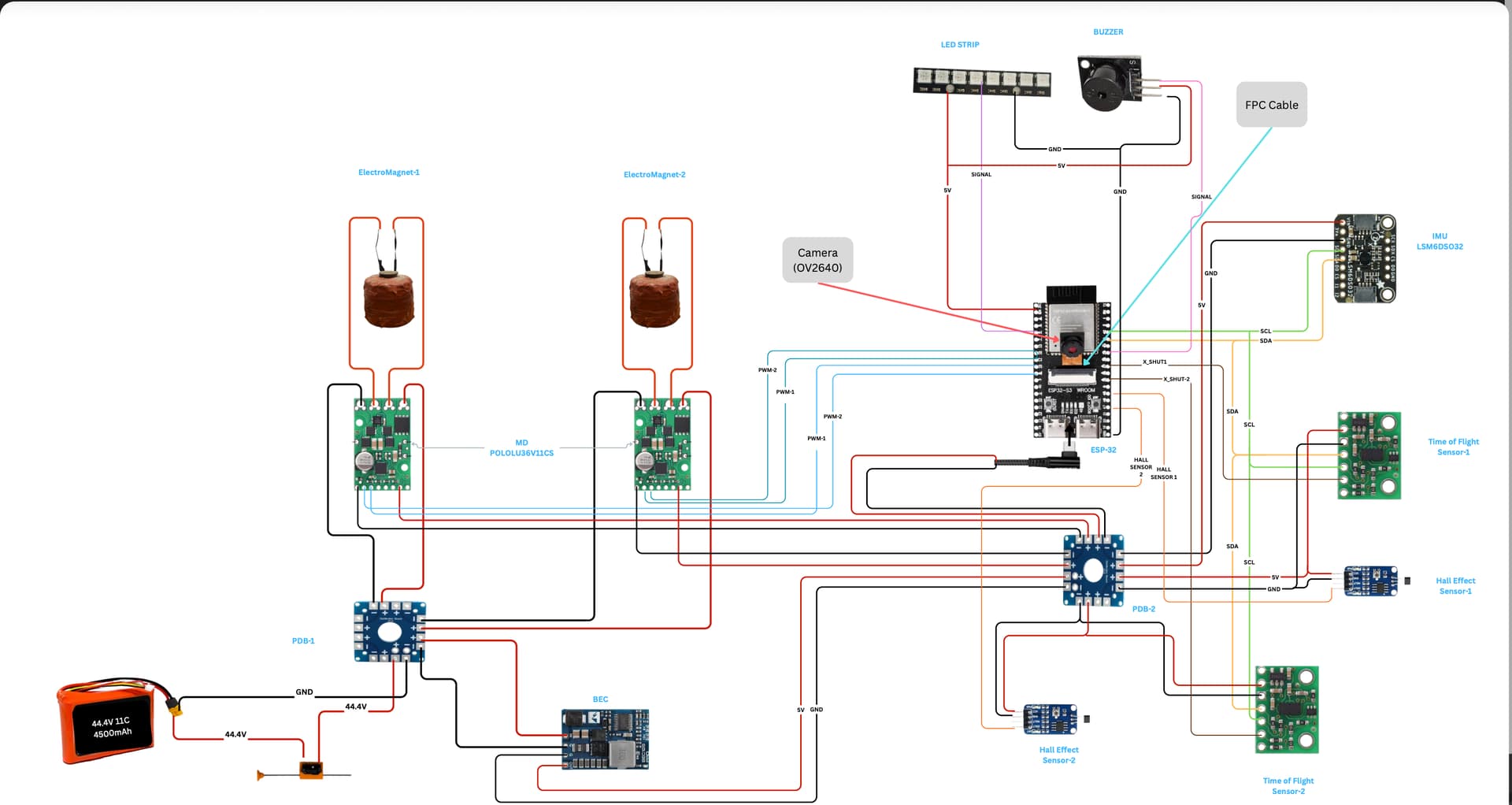
I am attaching the circuit diagram, and here is the video link showing our setup in operation (although a different motor driver was used at 22V). The project involves levitating a permanent magnet using two electromagnets.

Video Link: https://drive.google.com/file/d/1_7Z_h4rb8UcV2RijKO80dnNMi7-6Y5Of/view

Thank you again for your guidance.

Thank you for the additional information. I do not see any obvious issues standing out. Hopefully looking at it with a scope will reveal some more information.

Brandon