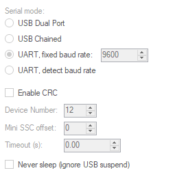
Hi Im trying to control the 18 channel maestro via serial from a ESP32cam. Ive made all the connections as per the documentation, and each device is hooked up to a adequate power supply. Ive set all the proper setting in the maestro control center windows app, and Ive upgraded the firmware to 1.03. Ive tried a baud rate 9600 and 115200. and neither seems to get a response from the maestro. The yellow status LED is blinking about ~once a second. Are none of the servos enabled, if so how do I enable them.
The servo I have on channel is unpowered (moveable by hand) even with 5V on the servo rails
Here is my code, which is just modified basic example
#include <PololuMaestro.h>

#define maestroSerial Serial1

MiniMaestro maestro(maestroSerial);

void setup()
{
  // Set the serial baud rate.
  maestroSerial.begin(9600);
}

void loop()
{

  // Set the target of channel 0 to 1500 us, and wait 2 seconds.
  maestro.setTarget(0, 448);
  delay(2000);

  // Set the target of channel 0 to 1750 us, and wait 2 seconds.
  maestro.setTarget(0, 1500);
  delay(2000);

  // Set the target of channel 0 to 1250 us, and wait 2 seconds.
  maestro.setTarget(0, 2448);
  delay(2000);
}
We have not tried our Arduino library for the Maestro with an ESP32cam; however, before getting to that or your code, I recommend that you try moving your servo from the sliders in the Maestro Control Center software first to make sure everything is working with the Maestro side of your setup. To do this, please disconnect the ESP32cam from the Maestro, connect the Maestro to your computer via USB, and open the Maestro Control Center.
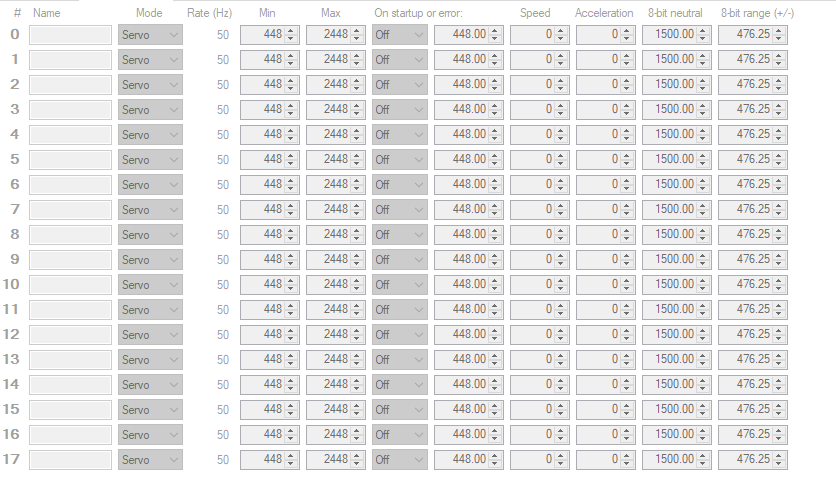
In your pictures, the GUI for the Maestro Control Center looks grayed out, which means your Maestro was not connected. If the Maestro does not automatically connect when you open the software, please use the drop-down menu at the top to select it (you should see it listed by its serial number if it is successfully connecting to your PC). Then, you can try moving the slider for the channel associated with your servo from the “Status” tab and see if your servo responds.
By the way, it looks like you might have configured the min and max settings for all of your Maestro channels to be well outside of the standard 1-2ms pulse width for RC hobby servos. Please note that it is possible to damage a servo by driving it beyond its physical limits, so I recommend using the default min and max (992 and 2000 respectively) for now. If you need to expand it later, I recommend following the procedure described in the “FAQs” tab of the Maestro product page for “How do I use my Maestro servo controller to get the maximum possible range of motion from my servo” to safely expand the usable range.
If you cannot get the servos to move from the sliders in the Maestro Control Center, could you post some pictures of your setup that show all of your connections?
Hi Brandon thanks for the reply.
I have tested a servo while using the windows control app and it was working fine. So I dont think its the servo or power supply. My power supply is large bench unit as well. Also the default 992 & 2000 only provided 90 degrees of the total 180 degrees. As far as I can tell the servo was undamaged. I also just tried an arduino due with a baud of 9600 & 115200, and Im still getting the blinking yellow status LED on the maestro. The servo is also unpowered (moves freely. The servo rail is at 5V, checked with a voltmeter.
Thank you for the additional information. Could you post some pictures of your setup that show all of your connections?
By the way, the setTarget() command accepts target values with units of quarter-microseconds, so it looks like you need to multiply your target values by 4 (i.e. to set the target to 1500µs, you would use a target value of 6000). If you send a target value outside of the min-max range configured in the Channel Settings tab of the Maestro Control Center, the Maestro will use the corresponding min or max value instead, so this likely isn’t the entire problem since your servo isn’t even holding (although there might be some digital servos that work that way).
Hi Brandon,
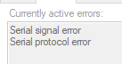
I tried changing the values in my code by multiplying them by 4. The maestro now displays a red error led which reads as a serial signal error and serial protocol error according to the app.
I also tried my micro maestro and i cant get it to work either (same error)
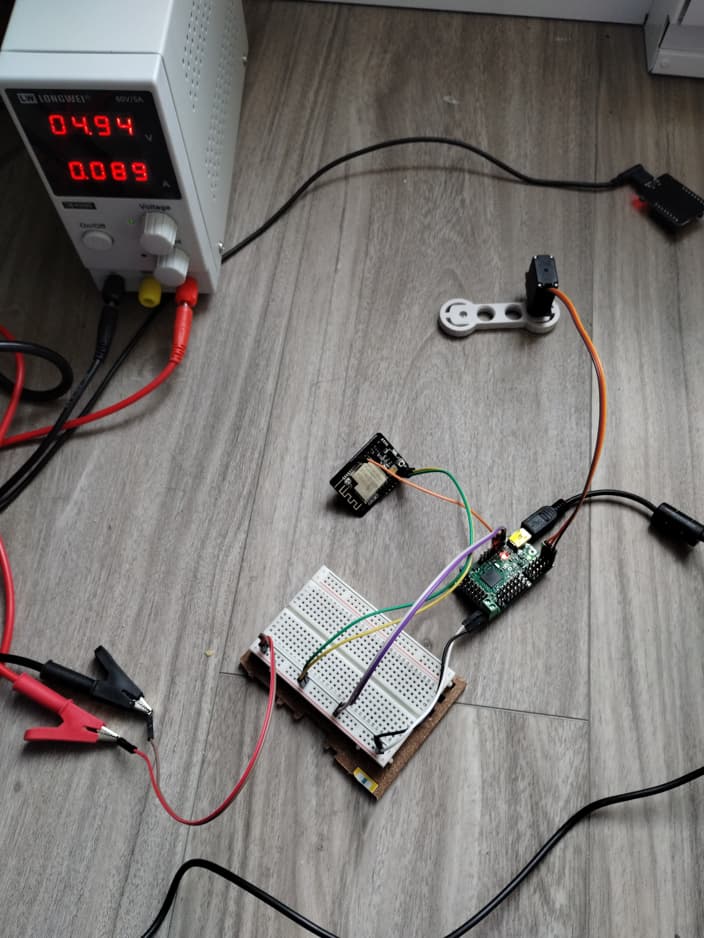
Heres my setup. 5v from power supply to ESP32cam & maestro inputs. Ive tried with USB and without to the maestro
Could you post the updated code that you’re using now?
It looks like you’re using Serial1 in your code, but from what I can tell, it looks like you might be connecting to the pins for UART0 (GPIO1 and GPIO3), which seem to normally be accessed through Serial. Can you confirm if those are the pins you are using?