Greetings Forum:
I am attempting to use the Arduino USB Host Shield to allow control of motors with the Arduino Dual MC33926 Motor Driver Shield and an Xbox Controller.
I know the Motor Driver Shield works independently, and I know the USB Host Shield works independently, but I haven’t been able to make them work well together.
No matter which joystick I use to control a certain motor, only one motor moves and only in one direction. It doesn’t matter what I have programmed in. Both joysticks will control one motor, and only in one direction.
I believe the USB Shield is creating some type of electrical noise that is being interpreted as a signal by the Motor Driver, but I can’t figure out if that’s actually the issue.
Additionally, the Motor Driver is reporting a fault, but exactly what a fault entails, I’m not sure. I don’t believe possible causes of the fault are listed in the user guide either.
08/06/16 Update: I unplugged all PWM and direction wires and the motors still move when I move the joysticks. Somehow the signal is going from the Output Pin to the Input Pin on the shield without having the intended physical connection.
Any suggestions or tips?
Thank you
Hello.
Which pins does your Arduino USB Host Shield use to communicate with the Arduino? Do you have any documentation for it?
How did you unplug only the PWM and direction wires? Are you using jumper wires to connect the motor driver shield to the Arduino? Can you post pictures that show how everything is connected including any soldered connections you have made?
-Nathan
Nathan,
From my understanding, it only uses the ISP connections, but now that I think about it. I never looked at the documentation (stupid of me) for the shield since it was working fine.
Here’s the shield I am using: http://www.sainsmart.com/sainsmart-usb-host-android-adk-shield-2-0-for-arduino-uno-mega-r3-mega2560-duemilanove-nano-robot.html
This is my setup. Arduino, with the USB Host Shield stacked on top, then the Motor Driver shield above it.
https://drive.google.com/open?id=0ByT0AUan3n9ydk5adzA4U1FEZFU
The library functions for the motor controller are set to operate on certain pins, and then those pins are to be jumped to the corresponding pins on the motor controller.
Example: Pin 7 is for the motor one direction pin so I have that pin (7) jumped to M1DIR on the motor controller.
I physically disconnected the jumper wires going from the motor pins on the Motor Driver DI/O side and the motors still functioned with different sketch that doesn’t use the USB Host Shield. I tried to run the Demo sketch and I’m getting a fault.
Thanks
I do not have permissions to view that picture you linked to. Can you check how you have shared it? Also, which Arduino board are you using?
-Nathan
Apologies, you should be able to view it now.
I am using the Uno.
The headers that mate with the Arduino’s headers are internally connected to the auxiliary header we placed opposite the screw terminals, so the jumpers you have connected between the two are not doing what you probably expect them to be doing. If you did not remap any pins on the shield, the extra connections probably did not hurt anything, but are redundant. If you did remap some pins, then you could be connecting two different signals to the same pin, which could damage the Arduino or driver. Either way you should remove those extra jumpers.
The SF pin (which provides fault information from the motor shield to the Arduino) uses Pin 12, which is also the MISO pin (used by the SPI connection for the USB host shield) so I would expect that to cause some trouble with fault detection.
There are directions for customizing the board to change the I/O pins used in the Remapping the Arduino Connections section of the user’s guide of the shield, though if you are new to working with electronics, you might remove the motor driver shield from the stack and just use the auxiliary connectors for testing until you have found a pin configuration that works for your application before you permanently modify the board.
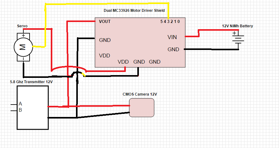
Also, I notice you have a lot of power connections to the board. If you post a diagram here that shows what devices you are using and how they are connected, I can look for any problems there.
-Nathan
Ahhhhh, that explains a lot. I had the feeling when the same things were happening when I removed the jumpers. They are now removed.
I see, I will go ahead and use the auxiliary connectors for now while testing.
Here is a schematic, sorry for the quality, haha.
Additionally, I’ve tested without having anything connected to the Motor Driver, and it did not seem to make a difference.
And thank you for the help thus far.
Thanks for the power schematic. I do not think this is directly related to your problem, however, many servos draw more than the 300-500mA the linear voltage regulator on the 5V pin of the UNO can provide, so we generally would not recommend powering the servo from there.
To verify what you said earlier, the Motor Driver shield and the USB host shield both seem to work if used independently, correct? It sounds like Pin 12 and possibly Pin 10 have uses for both shields, so you should use different pins for those two connections on the motor driver shield. The Arduino library code we have for the motor driver relies on those pins, so you will need to write some code to use different pins. This tutorial on the Arduino web site might be a helpful reference for you to understand how to generate a PWM signal on Arduino pins.
-Nathan
Thanks for the tip, I will look for a different way to power it.
That is correct. The demo works by itself, and the example codes for the USB Host Shield works well, and these work whilst all being stacked on each other in the current configuration. I even controlled the servo with the Xbox controller. The only issue is when I try and integrate the two shields.
Since Pin 10 can not be coded for a different output, should I cut the physical copper connection from Pin 10 to the M2PWM pin? And then write my own function that utilizes a different PWM Pin?
Yes, the Remapping the Arduino Connections section of the user’s guide I mentioned before has directions for cutting the copper, though you might want to connect everything using the auxiliary pins before you modify the board. Note that doing either of those will require you to write different code to use the board.
I’ve cut the connections for 9,10, and 12 to the auxiliary pins, and jumped 5 and 6. I changed the PWM values in the header file to 5 and 6, and erased the Timer 1 configuration code in the setup, and removed the portions in the SetSpeed functions that set some property of the Timer, but left the analogWrite statement that maps the speed value.
It does not work, but now it acts different then before.
The Demo sketch does not work correctly with pins 5 and 6 coded in, with or without the Timer code. It gives a fault in both cases.
Is the Timer configuration necessary? Could that now be the cause of my problem?
I seem to have it working now, finally. I reinserted the Timer configuration code in the setup and just removed the portions in the SetSpeed functions that set OCR1A to speed, and it it’s working pretty damn well now, I’m super happy, haha. Although I’m not entirely sure why it works now…haha.
Thank you so much, Nathan. Your help was very much appreciated.
Hi ElGalloNegro,
at the time I’m writting this I’m building a similar car with a similar setup.
Would you be so very kind to send me your sketch, because this one is little bit to difficult with my knowledge now.
Josua
Edit: It’s a very important project from my Highschool and one third of my grade