
Hello - I am trying to write a simple code in PicBASIC Pro to control a single stepper motor to run back and forth using the DRV8711 board. Unfortunately, I am not an Arduino guy, so I am not getting far trying to decipher Arduino code. I have been pouring through the data sheet and am under the impression that all I need to do is send the code (via SPI) to enable the board ($0C10) and just accept all of the other default values (registers). Then, I should be able to pulse the STEP pin and run the motor. But, this is not working. Does anyone have any experience with this? Thanks! Jeff
Hello.
You should be able to use STEP pulses after enabling the driver, but please note that by default the current limit is set to the maximum (~18A) so you should make sure you set it to something appropriate for your stepper motor and driver before activating the outputs, otherwise it could quickly damage something. This is done by setting a combination of the TORQUE register and the ISGAIN bits of the CTRL register (bit 7). You will also need to know the Risense value, which depends on which product you have (we have multiple boards that use the DRV8711 driver). You can refer to the implementation of the setCurrentMilliamps functions found in HighPowerStepperDriver.h from our Arduino library for more details. If you need more help with this, please let me know which specific product you are using as well as details about your stepper motor.
Once the current limit settings are configured appropriately, you can enable the driver by setting the ENBL bit of the CTRL register (bit 0) to 1.
Brandon
Brandon - Thank you for your quick reply. I am using the 36V4 board (p/n: 3730) with a 2A/phase stepper running at 12VDC. In my code, I am sending a TORQUE register value of 0b0001000110000000 which I believe sets the torque to 1/2 of it’s full range of 4A. I am then sending a CTRL register value of 0b0000110000010001 which I believe should enable the motor. You mention setting the ISGAIN bits of the CTRL register. I looked at the setCurrentMilliamps link that you sent, but as I mentioned, I am not a “C” person and was not able to make much sense of what I saw there. I have 2 of these boards and I think I have damaged one as the 5Vout on it is about 1.75V. The other one is still showing 5V, so hopefully, it is still functional. I have ordered a new “virgin” board to try once I am confident that I won’t fry it (with your help). Are there things that I can look at to verify that my one board is not damaged as well? Thank you in advance for your help. Let me know if there is any additional info you need from me. Jeff
As I mentioned before, the maximum current limit that the chip allows you to set is around 18A (4A per phase is the limit that our board can do without additional cooling). From the values you posted, it looks like you’re setting the current limit to over 9A per phase.
From page 14 of the DRV8711 datasheet the equation for calculating the current limit is:
I_{CHOP} = \frac{2.75 \text{V} \times TORQUE }{ 256 \times ISGAIN \times R_{ISENSE} }
Where I_{CHOP} is the current limit in amps and R_{ISENSE} is the current sense resistor in ohms. For the #3730 High-Power Stepper Motor Driver 36v4, R_{ISENSE} is 30 milliohms. So, to set the current limit to 2A per phase for your motor:
2 = \frac{2.75 \times TORQUE }{ 256 \times ISGAIN \times \frac{30}{1000} }
Rearranging to solve for TORQUE in terms of ISGAIN:
TORQUE = \frac{15360}{2750} \times ISGAIN
Our library tries to use the highest ISGAIN setting (which is 40 and achieved by setting both ISGAIN bits high), then checks to see if that results in a TORQUE value higher than 0xFF. If it does, then we need to use a lower ISGAIN so the TOQRUE value fits within 8 bits. However, in your case, to set it to 2A per phase on the High-Power Motor Driver 36v4, an ISGAIN of 40 is fine since if we plug 40 into our equation TORQUE is less than 255:
TORQUE = \frac{15360}{2750} \times = 223.418
So, I recommend setting the TORQUE bits of the TORQUE register to 0b000011011111 (i.e. 223 in decimal) and the CTRL register bits to 0b111100010001 (which should set the ISGAIN to 40 and enable the driver).
As far as testing to see if your board is still working, you might start by seeing if you can just read some of the registers.
Brandon
Brandon - Thank you for the nice description and breakdown of the calculations. I will give the new values a try and see what happens. Will let you know!!! Thanks! Jeff
1 Like
OK, I tried sending the new TORQUE (0b0001000011011111 or 10DF Hex) and CTRL (0b0000111100010001 or 0F11 hex) values that you calculated and I still get nothing. I am sending the TORQUE register first. I just received the new board I ordered and tried it as well and still get no results. I am using a benchtop power supply and when I run my code, I only see that it is drawing about 30 mA which is normal for driving the 3 LEDs on my board. I see no evidence that the driver boards are drawing any current. Shouldn’t I see some increased current draw when I enable the motors? Unfortunately, I can’t read the registers as I have no way of displaying any results. My FAULT pin is 5V (indicating no fault) and the 5Vout pin is 4.98V. I have the SLEEP pin pulled high. My power supply is limited to 2A, so I can’t see any way that I could damage my boards or the stepper. I measured the coils of the stepper and get 2.2 ohms between A+ and A- and the same between B+ and B-. I am at wits end. Any thoughts? Jeff
Could you post more details about your connections as well as some pictures of your setup that show all of the connections? Also, could you post the simplest but complete code that demonstrates the problem?
By the way, please note that the current draw shown at your power supply will generally be lower than the current that’s actually going through the coils since they are essentially at different voltages. For example, your power supply can output 12V at 2A, which is 24W. In comparison, according to the resistance you measured, your stepper motor coil is rated for drawing 2A at around 4.4V, which is only 8.8W. So, if the current limit is not set appropriately, it can still draw much more than 2A through the coil while using less than 2A from the power supply.
Brandon
Brandon - Point taken about the current. I was just thinking that I should see something current-wise that would change once I enabled the motor that would indicate that something was happening…
Stepper2 Test.bas (2.7 KB)

I have uploaded my code and a snip of my board design. Notes: green = 5V, red = 12V, blue = Gnd, black = signal. The view is as though you are looking down on the board with the components on top and viewing the circuit traces underneath (as though the board was clear). The attached code is just for the driver board labeled Stepper2.
I really appreciate your help and patience. I just know it is something stupid that I am doing wrong. Please let me know if you need anything else. Thanks! Jeff
Thank you for the additional information. I do not see any obvious issues with those connections or your code. Could you try looking at the signals you’re sending with an oscilloscope and posting some screen captures of them?
Also, could you post some pictures of your actual setup that show all of your connections, as well as some close-up pictures of both sides of the driver board if that is practical for your setup?
Brandon
Brandon - Over the weekend, I built a board that uses the DRV8825 board so that I could test the steppers that I have and it works just fine. I am able to drive both a 2A and 4A/phase motors (at reduced current, of course). As soon as I enable them, I see a current readout on my power supply - signs of life that I do not see on the 8711 boards. So, I am going to build a similar new board for the 8711. This will just be focused on one driver and nothing else. My other board had several other functions, so I am stripping all that away just to eliminate variables. I am also going to add an LCD so that I can query the board and see the results. Unfortunately, I do not have access to a scope, so I won’t be able to provide that info. I should have this built today and will let you know what I see. Thanks! Jeff
Brandon - SUCCESS!!! My new board helped me solve my problems which were 2 in number. First, I was appending the R/W bit and the address to the wrong end of my register values and 2nd, I was sending the values out as LSB first. Once I figured those 2 things out, the driver board works perfectly. Once I clean up my new code, I will post it. I was so happy to see that motor spin! Thank you for your help and patience.
So, now I have a related question that I think I know the answer to, but want to check with you first. I also have the 8A versions of this board (36v8). Do all of the calculations for the 36v4 apply to the 36v8 board? Specifically, is the Risense value for this board 30 as well? My intent is to run a 4A/phase motor at full current using the 36v8 board. If so and I do the calculations, I will have a ISGAIN of 20 and the TORQUE register will stay the same at 223, which makes sense as I am doubling the current and halving the ISGAIN value.
Jeff
1 Like
I am glad to hear you were able to get it working! Thank you for letting us know.
The High-Power Motor Driver 36v8 uses a 15 milliohm Risense resistor. So, using the same TORQUE and ISGAIN values (223 and 40, respectively) would set the current limit to 4A per phase.
Brandon
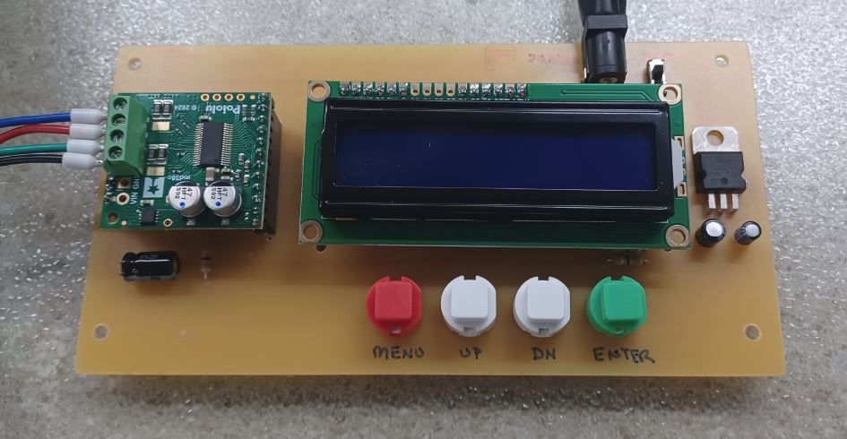
OK! I am posting my new code along with a picture of the new board and diagram of the circuit. Very happy to have this working now and hope the code gets other PicBASIC Pro users going. Thank you Brandon for helping me out. Great customer service!!! Jeff
Pololu Stepper-DRV8711.bas (3.6 KB)

1 Like