Hello,
I recently purchased the VNH5019 dual motor driver to run a 12V, 6A brushed DC motor with an incremental rotary encoder for speed feedback. I would like to implement a software user interface so that the speed can be adjusted and monitored by the user through that interface. I have used MATLAB before and I was thinking of getting MATLAB GUI to communicate with Arduino to achieve this. However, I realised that the VNH5019 library cannot be imported into the MATLAB and that I would need to write a MATLAB library myself if I want to do that.
So because of that, I looked into third party ‘user interface’ programs available for Arduino IDE which didn’t look too promising.
I was wondering if you have any suggestions for my project and that if you could please assist me with finding a proper user interface to pairwith VNH5019.
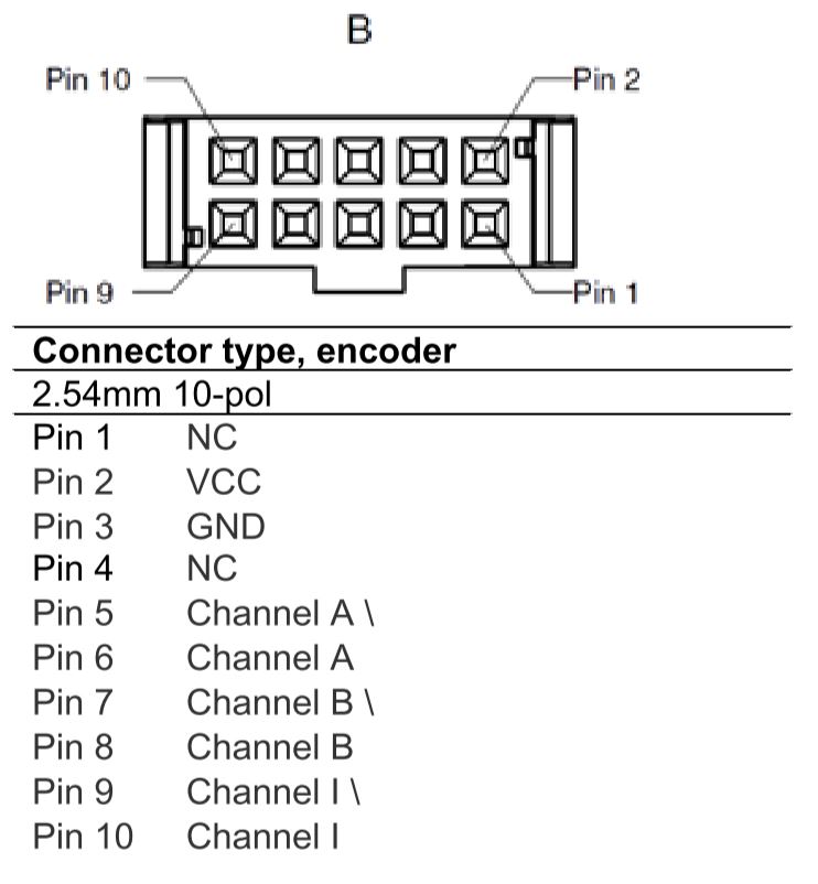
I also wanted to know if it is possible to get a speed feedback through VNH5019. (my guess is to use the analogue pins on the shield). I have attached a section of the datasheet for the encoder, however, I will only be using channel A since this isn’t a bi-directional application.
Thanks,
Payman
Hello, Payman.
The dual VNH5019 motor driver shield is just a motor driver and does not support speed control. However, you can implement closed-loop speed control with your rotary encoder by using one of the Arduino’s I/O pins to read your encoder’s output and set your motor’s speed.
We do not have or know of any user interfaces for the Dual VNH5019 motor driver shield. Our only suggestion would be to write your program and test it using the Arduino IDE before trying to build a user interface either using MATLAB or something else.
- Amanda
Hi Amanda,
Thanks for the reply. Do you recommend using a PD control system to monitor the current and adjust the motor speed accordingly? PD control concept is fairly new to me so I still have to look into it further, but I just want to make sure I am on the right track and that VNH5019 is capable of PD control.
Thanks,
Payman
The dual VNH5019 motor driver shield allows you to control the average voltage applied to your motor, and in general there is nothing that would prevent you from using it as part of a larger system that does PD or PID control.
Can you provide more details about your project and what exactly you are trying to do? Without knowing more about the application, I cannot say if using PD control could be appropriate or not.
By the way, in case you have not already seen, you might find this Wikipedia article on PID control helpful. There are also several good tips and suggestions for PID tuning on our forum.
- Amanda
We are using this motor to drive a centrifugal pump with a pressure that could approximately reach 400mmhg. So there is going to be variable load on the motor. We also need to be able to keep the speed constant under these loads and change the speed when needed.
I did some research on PID and it seems that it is the suitable control system. I am just wondering if there are any simpler methods that would enable me to do the same thing.
PID is the most widely used feedback control algorithm for systems requiring continuous modulating control. There are other alternatives for PID control, but I am not sure how feasible it is to implement them for your application.
By the way, instead of using the dual VNH5019 motor driver shield, you might consider using one of our Jrk motor controllers with feedback, which support closed-loop speed control with configurable PID period and PID constants. You can find more information in the Jrk motor controller user’s guides, which are linked under the “Resources” tab on any Jrk product page.
- Amanda
Unfortunately I won’t be able to purchase another board due to budget and time limitations of my project. However, from my understanding, I should be able to use the free pins on the shield as rotary encoder inputs for arduino and then design my PID control system using software (Simulink). I think as long as VNH5019 allows for data to be sent through its free pins there should be any problem.
As for a simple user interface for the Arduino, I have found Nextion LCD touchscreen displays to be powerful, easy to use and to program. Here are a couple of Youtube videos I found helpful.
Thanks for that, I think at this point I will be using Simulink to program the Arduino board and VNH5019 as it is easier to implement the control system. The Simulink interface won’t be as user friendly as these touch screens but I have time and budget limitations so I have to work with what I have. I am still working on the control system model design and will update this thread when I have made progress.
I managed to make a communication channel between Arduino and Simulink. However, my output voltage to the motor is very low (~2V) and I am using a 9V battery. I am using a S-function block in Simulink to convert the C code and C libraries of VNH5019 to Matlab code. I can’t seem to find the issue. I appreciate it if you could help me with this. (I feel that there is an issue in converting the C code to MATLAB)
We generally do not recommend 9V batteries for motor applications, since they cannot source much current. The 9V battery not supplying enough could be why you are getting a low output voltage. Can you change the power supply and see if that changes anything?
For any issues with Simulink and MATLAB, I recommend contacting MathWorks support. (By the way, the Arduino library for the dual VNH5019 motor driver shield is written in C++, not C.)
- Amanda
I’m only using 9V battery for testing and validation purposes. I managed to fix the issue by adding a simulink PWM block on the corresponding arduino pin (pin 9 for motor 1). Thanks for the help, I think as you said this project will be more Simulink oriented after this point and I will ask my questions in Matlab forums.