Hi,
I’d like to connect 4x Tic36v4 on a I2C port of RPi4. Probably the ERR and !RST as well. The idea is to drive those 4 steppers:
2x NEMA11
1x NEMA17
1x NEMA23
As RPi4 is NOT 5V tolerant and I will not count on diode protection, could you please advise me on some level shifters to use?
Thx for your help,
Stephane
with the same setup as Stephane,
I’m using the #2595 4-channel, bidirectional, logic level shifters you advised,
And it’s working pretty fine for the SDA, SCL and !RST pins of the TIC36V4.
The only problem is the ERR pin, normally it’s at 0 until there is an error, but as soon as I connect it to the RPi4) threw the level shifter, it sets the ERR pin at 1 or at least the TIC puts itself in error mode (with the red LED).
(The GPIO pin on the RPi is set as input with a pull down resistor at 0, once connected to the level shifter it goes to one,
The TIC’s ERR pin is at 0 as it has not detected any error, once connected to the level shifter ERR pin is at 1).
Do you have any advice by any chance, did I miss something ?
A good day in all cases.
Could you try walking through the following steps and reporting the voltages you measure?
Remove the connections you’re making to the ERR pin (both between the Raspberry Pi and the level shifter, as well as the level shifter and Tic).
Measure the voltage at the Raspberry Pi GPIO pin you’re using.
Connect the Raspberry Pi GPIO pin to a pin on the low voltage side of the level shifter and measure the voltage on corresponding pin on the high voltage side.
Measure the voltage on the Tic’s ERR pin.
Connect the level shifter to the Tic’s ERR pin and measure the voltage again.
Also, could you post pictures of your setup that show all of your connections?
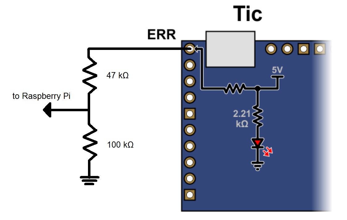
I suspect the pull-up on the level shifter pins is too strong and overpowering the pull-down on the Tic’s ERR pin. If you only need to read the ERR pin from the Rapberry Pi, you might try simply using a voltage divider to get that signal to an acceptable level instead. A divider with a total value of a few 10s or 100s of kΩ would probably be good; for example, something like this:
Thanks a lot for this answer,
This fix should do the trick.
But do you think that it would work if I change the resistances on this canal of the level shifter ? Like 100k resistances ?
Hello Brandon,
Or anybody with the patience to read about my issues
Still fighting with the I2C communication between TIC26V4 and RPI,
I managed to do lots of things, but the I2C communication is still so-so.
I have load of errors and the SCL and SDA signals don’t seem to be perfect so maybe my communications errors are due to this ?
If I test my program with the pigpio library, the SCL and SDA signals looks fine,
But once I add the TICs and level shifter,
The SCL doesn’t seem to come back to a real 0V,
And the SDA has some “glitchs” and is not really square.
I’m wondering if it’s the level shifter fault, or if it’s a problem of external pull-up.
It might also be a problem of delay, as usually I have communication errors while continuously asking the position of the motor in a homing or set_target_position.
What is the standard delay you would be using for I2C communication ? 0,1 s or nothing at all ?
I made a small doc trying configurations and external pull-ups to show the bad signals, if I could have your input on this it would be awesome
Have you changed the ERR pin circuit to what I suggested in my last post, and is the Tic is still indicating an error?
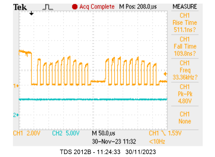
Your waveforms do not look especially concerning, but the fluctuating logic high voltage on the 5V side of the shifter does seem kind of strange. Could you post some updated pictures or diagrams showing all of your connections and indicate where you’ve added the pull-ups you mentioned? Also, could you post a copy of your Tic settings file? You can save a copy of your Tic settings file from the “File” drop-down menu of the Tic Control Center while the controller is connected.
Not yet for the ERR pin, so far I’m not using it at all.
Waiting for a new PCB.
The Tic is sometime indicating an error because of bad communication I’d say, but I’m sending an exit_safe_start or another set_target_position to exit the soft error state so that it continues to its desired target.
5V side, the fluctuating logic is indeed very weird, it almost looks like a condo charging and discharging,
But I still fin it weird that both on the 5V and 3,3V sides, there are some plateaus in the signals that are neither 0V neither 3,3 or 5V. Like just a small step. Sometimes the SCL is not even 4V after the level shifter, but perfectly 3,3V before the level shifter.
If I’m using the same I2C1 canal or another I2C3 on my RPI with a TLI hall sensor (without level shifter), the signal is square, 0 or 3,3V that’s all, no small plateaus.
On the picture,
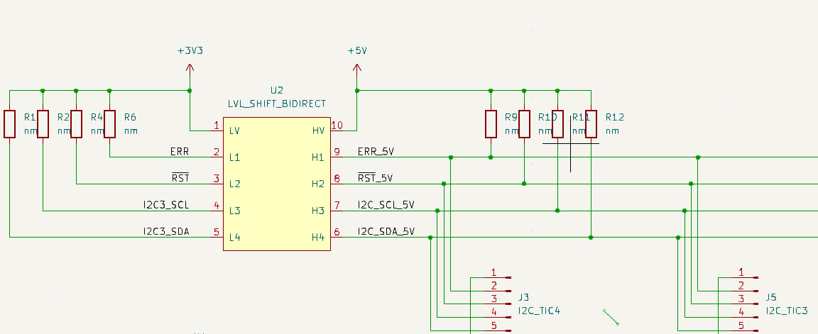
The ERR pin is not connected,
!RST pin is not connected,
I2C_SCL and I2C_SDA are connected threw the level shifter to SDA1 and SCL1 of my RPI4,
GND is connected to the GND of the RPI.
R11 and R12 are 10 Kohm (tried 2,2 and 47 kohm also) and all the other resistances are unmounted.
Here is a copy of my Tic’s settings file : tic_settings.txt (1.4 KB)
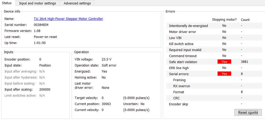
Could you connect the Tic to the Tic Control Center and monitor the Errors being indicated in the “Status” tab to confirm which specific errors you’re seeing?
There are 10k pull-up resistors built into the level shifter (in addition to the ones built into the Tic), so we generally do not expect external pull-ups to be necessary. Could you post a more complete schematic if you have one and some pictures of your actual setup in its current state? Also, could you try monitoring the 5V supply you’re using for the HV connection on the level shifter when you run the system?
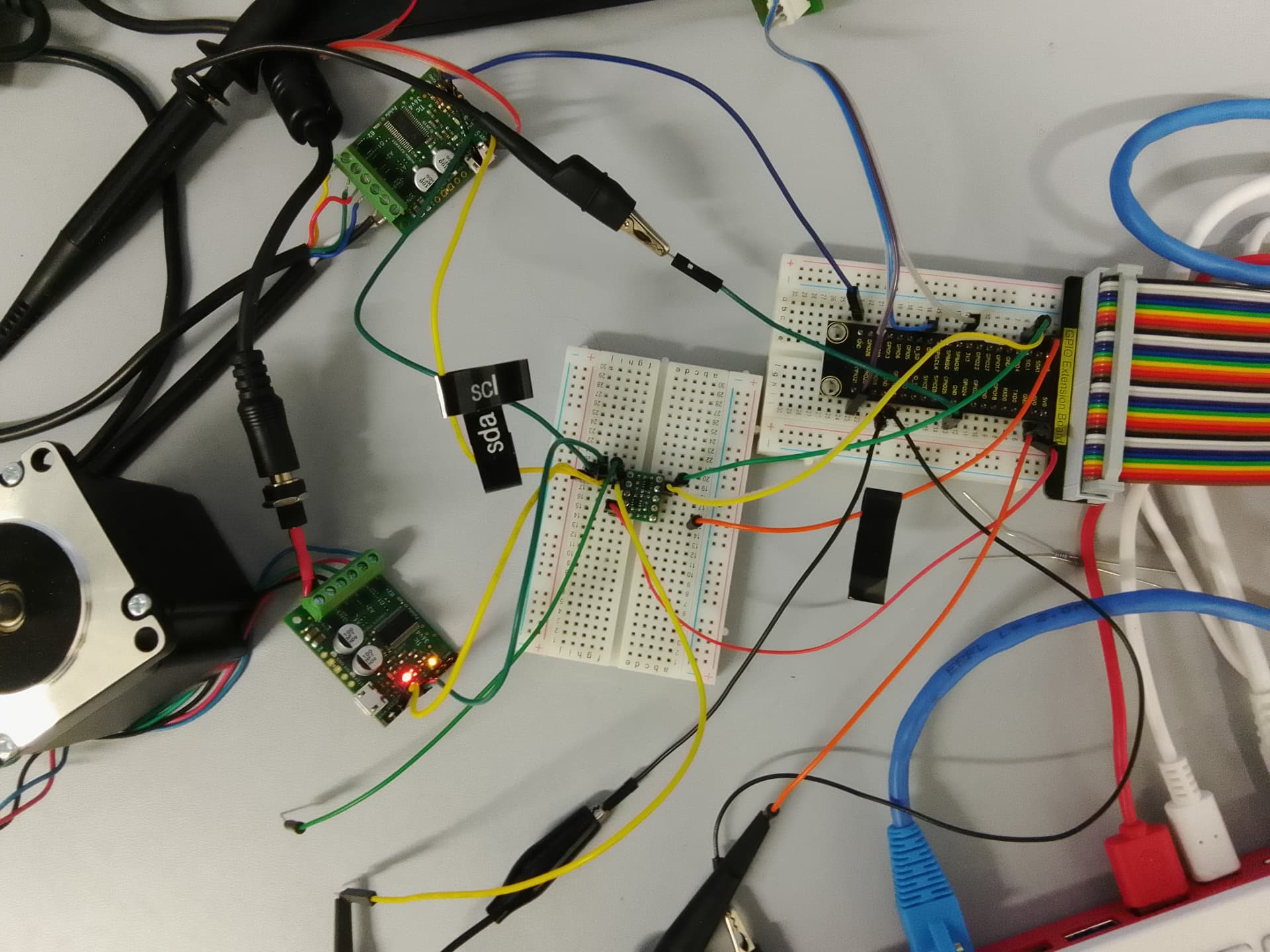
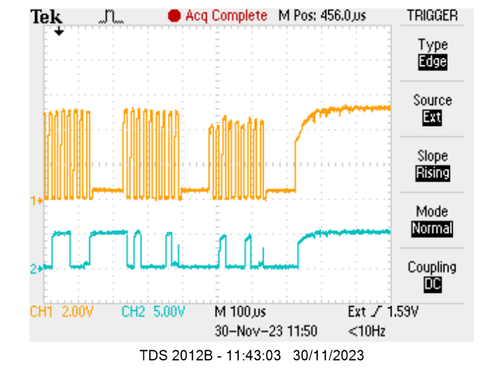
The picture of my set up while testing I2C problems :
No external 10k pull-up,
One probe of the oscillo on SCL on the 5V side of the level shifter,
One probe on the 5V from the RPI400
2 Tics out of 4 in the final set up are connected
The other device is just a hall sensor
Measure taken while sending a set_position(0) to one Tic
Now launching a set_target_position, trigger on the ERR pin,
“Last motor driver error : None”
Asking non stop the Tic without delays (I still have some error even though less with a delay of 0,1 or 0,2) get_current_position
The error I’m having and that is stopping the Tic (without my fiw which is to send exit_safe_start regularly) is “Serial error”
It looks like there’s a lot going on in your setup. Do you have a common ground connection between the Raspberry Pi and each Tic controller? It looks like you might have one of them grounded and not the other. Are both Tics triggering errors or just one? Also, could you post a copy of the code you’re using (preferably simplified down as much as possible while still exhibiting the problem)?
If you continue having problems after ensuring both of them share a common ground, could you try simplifying your setup down as much as possible (e.g. a single Tic controller, the level shifter, and your Raspberry Pi) while making the connections as direct as possible and see if anything changes?