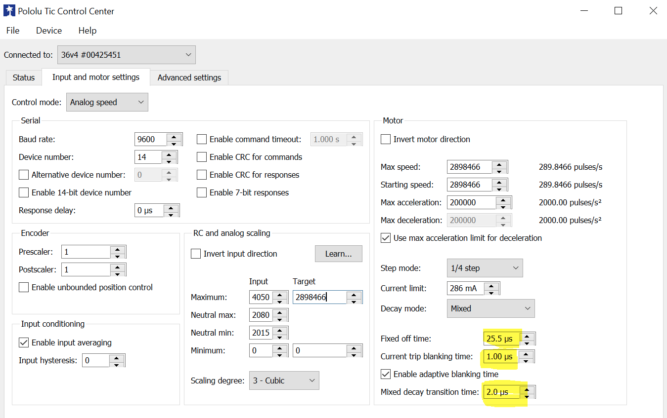
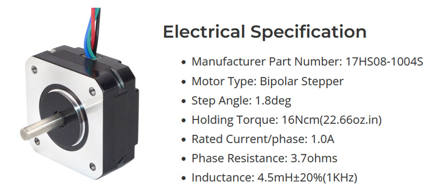
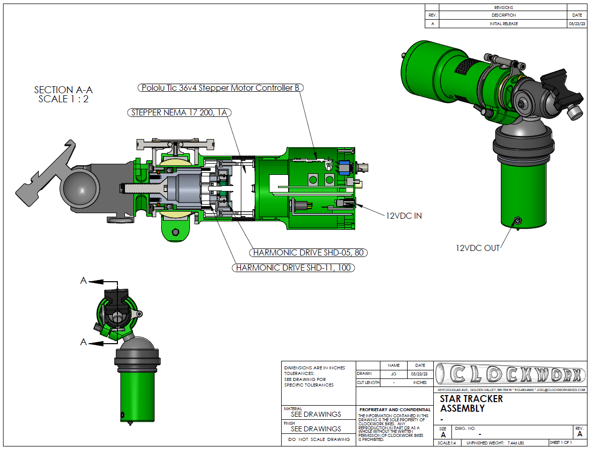
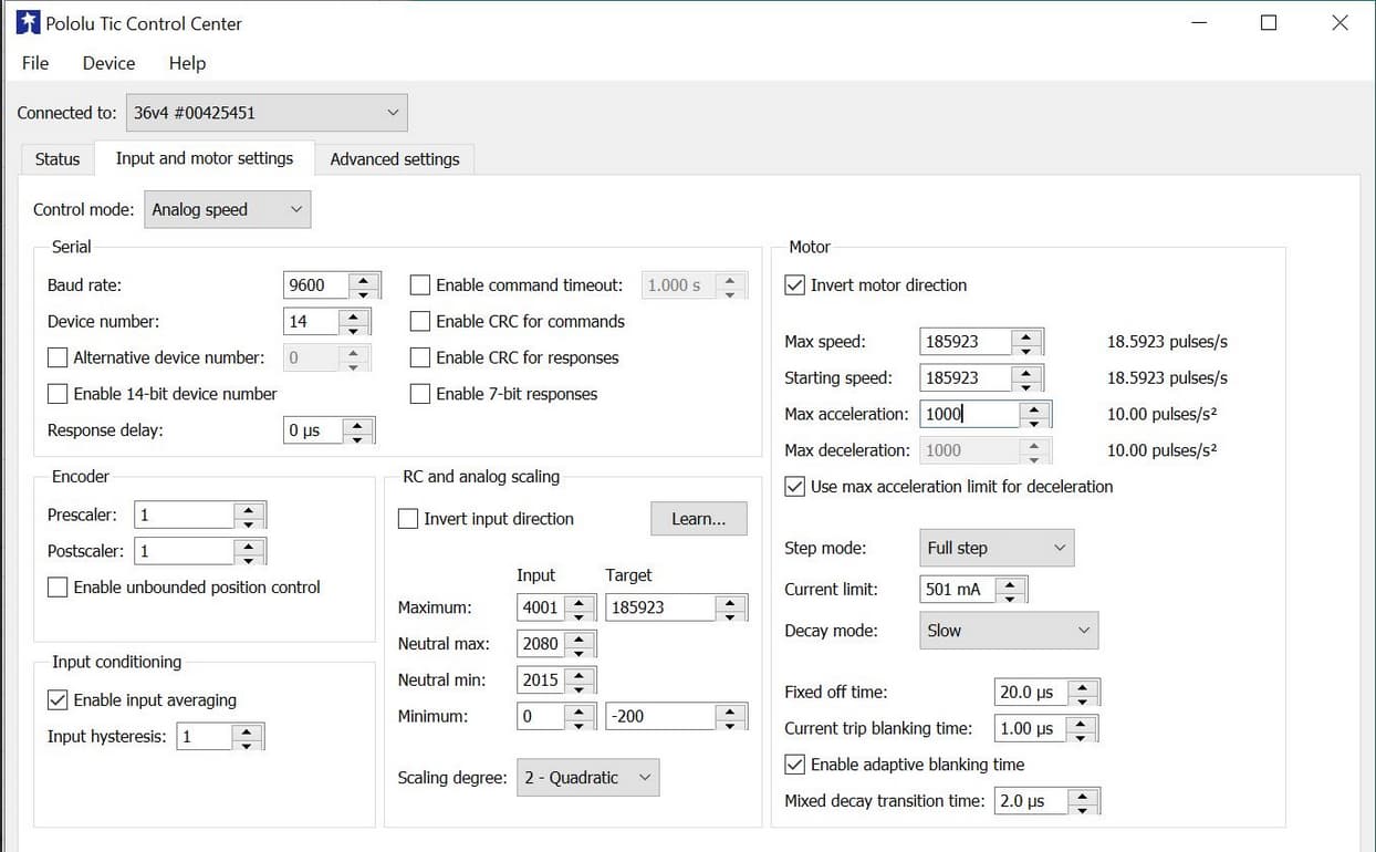
I’m using the below stepper motor with the Tic 36v4 controller and need it to only move at a constant speed of 22.22 RPM or 289.8466 steps/sec. I’ve got the speed dialed in but I’m unsure how to set the parameters in yellow? Changing these makes a big difference in how smooth the motor runs but I’m unsure of the ideal setting for this motor, micro steps, current, and speed. Is there a way to calculate this? Rule-of-thumb?
I referenced Pololu - 6. Setting reference and the TI documents but wasn’t able to apply the knowledge to my settings.
I do not have a general rule of thumb to suggest for optimal settings since it depends on the specifics of your setup such as the stepper motor and supply voltage, but if the default values are not good enough for your application, the best approach for tuning them is probably to look at the coil current with an oscilloscope current probe and try to adjust the values to get as close to a smooth sinusoidal waveform like the DRV8711 Decay Mode Setting Optimization app note demonstrates.
If you don’t have access to an oscilloscope with a current probe, it probably doesn’t hurt to try to adjust them based on the perceived smoothness of the motor that you were observing.
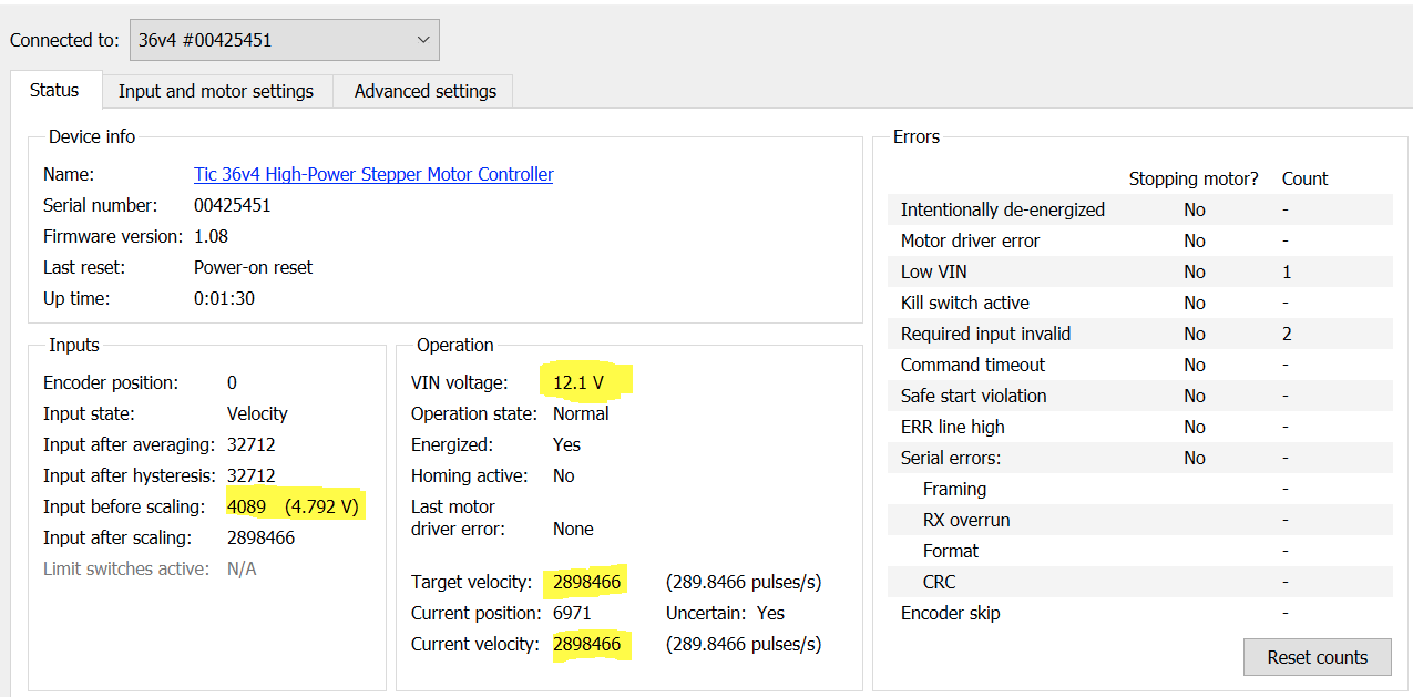
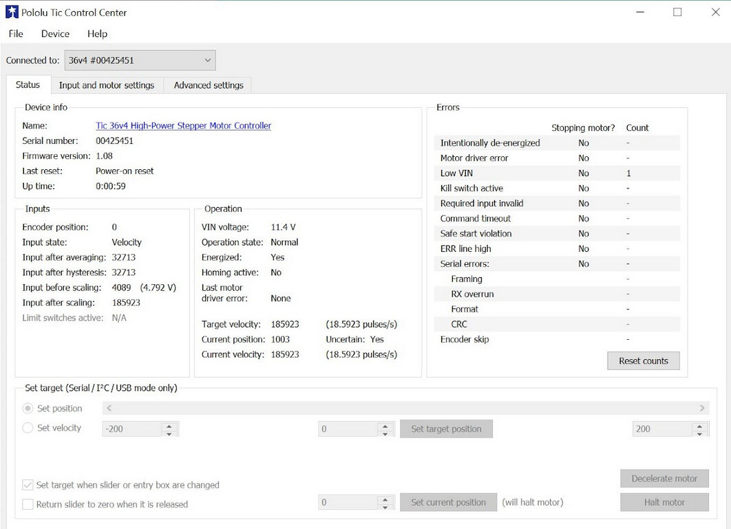
Thanks. My battery ranges from 12.3 - 8.5V and looks like the Tic is supplying 4.792V.
Playing with the settings will be fine but I’m wondering if there’s a limit to the fixed off time where the motor would loose torque?
It sounds like you might be misunderstanding the “Input before scaling” variable. To clarify, the “Input before scaling” variable is the reading that the Tic is taking from your analog or RC input; it is not a representation of the Tic’s output to the stepper motor.
I generally wouldn’t expect the off time setting to have a significant effect on the motor’s torque.
I’ve got things moving pretty well and hold a constant speed over 24 hrs. but when I look at smaller intervals, like 2 min., I’m seeing the speed change +/- 6%. This is going to be a problem since the motor is moving a camera that takes 2 min. exposures and the change in speed is noticeable.
Is the +/-6% precision the limit of the Tic or the motor? The Tic software shows the steps/sec. holding steady with 6 sig. figs. I’m guessing the speed change is due to the precision of the motor. Micro stepping doesn’t change the precision.
Is there anything that the Tic software can do to help? Check position and make corrections?
How are you measuring the speed, and can you quantify it in absolute terms instead of a percentage (i.e. how fast are you stepping the motor and how much is it varying by)?
Stepper motor control is inherently position based, so if you have the Tic stepping it at a constant rate, I generally expect the motor to step at that speed very accurately, unless it is missing steps (which wouldn’t explain it going faster than the set speed).
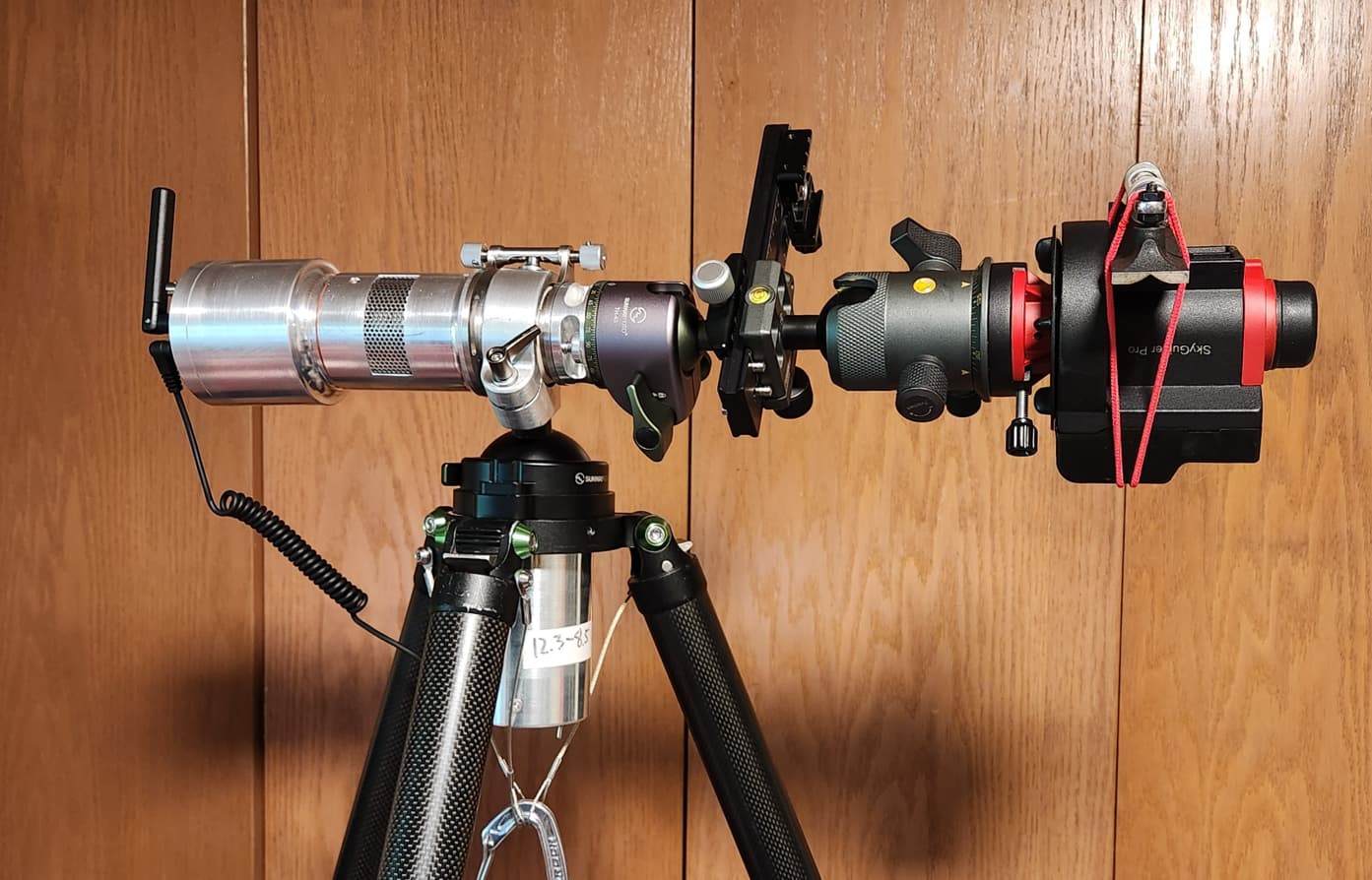
I’ve calibrated the correct speed empirically since there’s some unknown loss of speed when the calculated 15.8185 pps is used. The unit on the right is operating at the exact needed speed. My unit on the left is reversed so that when the speeds match, the right unit is static. At 2 min. I can tell if my unit is fast or slow based on which direction the right unit moves. For example, if my unit is slow and needs 5 sec. after 2 min. to move the right unit level, then I’m noting the speed is 4% off. I’m pretty sure the error is in the stepper motor.
These are variables I’ve tried changing and have gotten the same error rate:
Full, 1/2, 1/4, 1/8 microstepping
.143 to 1A
Changing decay mode
Adding payload 0-300 Ncm (after the 8000:1 gear reduction)
“Running start” to make sure acceleration wasn’t a factor
If you’re seeing that the speed seems accurate over a full day but varies on a shorter timescale, that does sound like it might be due to something mechanical, like the motor or your gearboxes not being exactly uniform. If you can monitor the inaccuracy carefully, you might be able to correlate it to revolutions of the motor or one of the gearboxes. Unfortunately, the Tic can’t really do anything to compensate for that since you would need to use closed-loop control with encoder feedback to sense the position of the motor, which the Tic does not support.
The Tic’s timing should be much more accurate than +/-6% (we expect speeds around what you’re using to have an accuracy on the order of a few thousandths of a percent).
How did you calculate your target speed of 15.8185 pps? With a 200 steps/rev motor and 8000:1 gear reduction, I would expect you to need 18.5185 pps to make exactly one revolution per solar day (86400 seconds), so I suspect that’s what you’re going for and 15.8185 was just a typo.
However, given that this is an astronomy application, could part of the discrepancy be from the difference between a solar day and a sidereal day? If you calculate what you’d need to get one revolution per sidereal day (86164.0905 seconds), you get 18.5692 pps, which looks a little closer to your empirically determined speed of 18.5923.
Thanks, Kevin. I’m pretty sure the issue is the speed precision since I can see the movement of stars. If it were just the speed accuracy I could compensate for that.
Given that, would a JrK and DC motor with speed monitoring be a better choice for my need for a constant speed?
It’s hard to say whether you would be able to get better accuracy with a Jrk and brushed DC motor, since that approach might have its own issues and challenges. If you’re still aiming for about 5.5 RPM like your latest Tic settings seem to show, that should be a reasonable speed for the Jrk to maintain with closed-loop speed control.
However, we expect stepper motors to be more suited for precise positioning applications in general, so I’d suggest trying to make sure it really is the stepper motor (or the way it’s being driven by the Tic) that is causing you problems. If you can determine that the inaccuracy is varying periodically every 200 steps, for example, that would give a pretty strong indication that it’s caused by the motor not turning uniformly.
Here’s a video attempting to show the variance. Speed up 4.65x so 4 seconds = 1 rotation (200 steps at 18.5923 pps). 1 graduation mark on the vial is 80 seconds (.02*). Stepper is moving too fast when bubble moves left and too slow when bubble moves right. At constant speed the bubble should remain stationary.
I tried configuring a Tic 36v4 with settings similar to yours and checked its output with an oscilloscope, but I didn’t see any jitter or other inaccuracy that looked like it would account for the error you are seeing.
You seemed to be using full step mode in your earlier screenshots; is that still the case? If so, I’d expect 18.6 pps to produce one revolution every 10.8 s, and if sped up by 4.65x that would be every 2.3 s. Still, it’s apparent that the error is varying on a much slower timescale (at least 1 minute in your video?) so it doesn’t seem to be directly linked to revolutions of the motor.
One thing we noticed in your screenshots is that you seemed to to be using analog speed control mode. Even though your input voltage seems to be comfortably above the input maximum used for scaling, I’m concerned that the input might occasionally fluctuate enough to change the target speed (for example due to electrical noise). If you haven’t already, could you try setting the input mode to Serial / I2C / USB and setting the target speed directly from the Status tab of the Control Center to see if that makes any difference?
If I understand correctly, you are testing with another device that is turning at the right speed so that if everything is accurate, its rotation and the Tic-and-stepper-motor system’s rotation should exactly cancel each other out. Are you confident that the other device is accurate? (Have you verified its accuracy and consistency some other way?)
Controlling with USB seems a little better than analog but not perfect. For the analog voltage I have a jump from 5V out to analog so it only does the max. when I flip the on switch. Would adding a 5V regulator decrease any fluctuations?
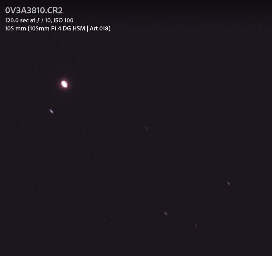
You’re correct on the test apparatus. I’m using the other device as a standard because it functions well and allows a 2 min. exposure with a 105mm lens and produces round stars. This is cropped 400%.
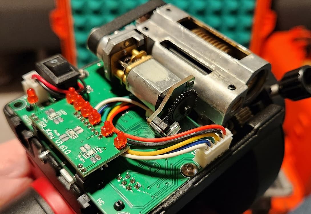
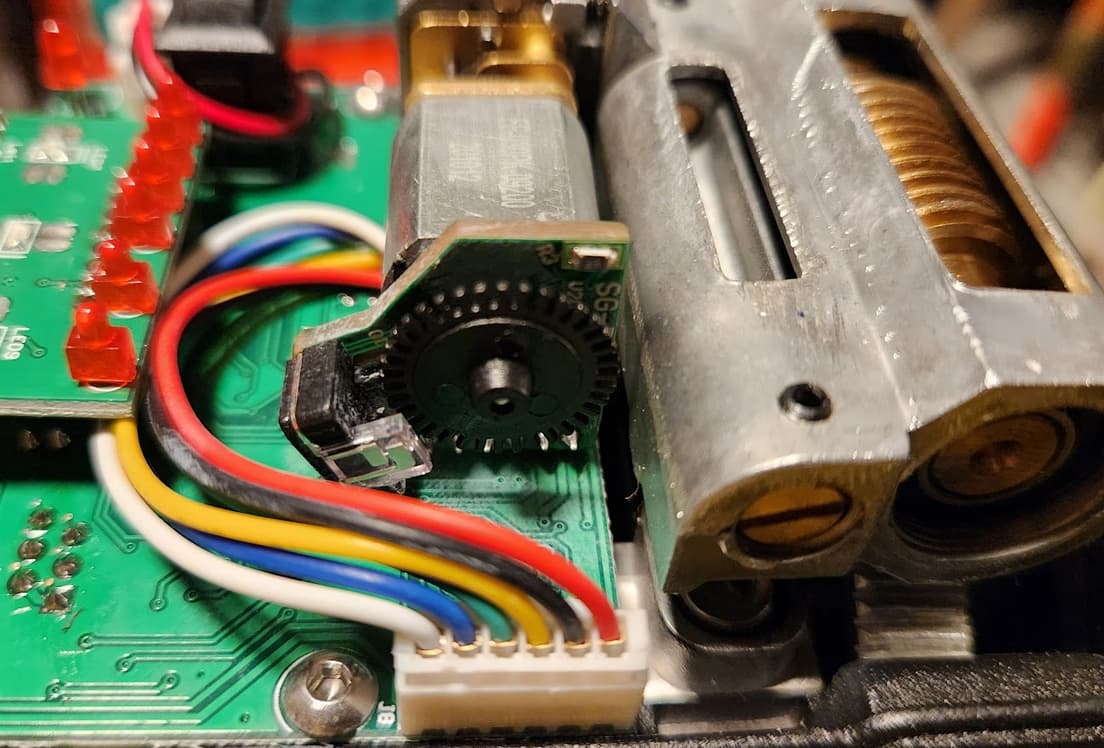
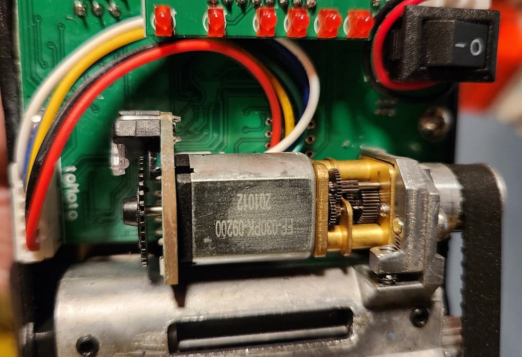
For reference, this is the standard device. It’s driven by a little DC motor, gear box, pulley, and then worm gear. Looks like it does have an encoder on the end of the motor where the shaft is spinning at the full motor speed.
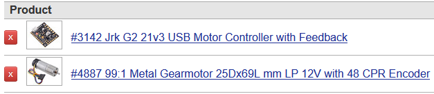
I’m trying the Pololu 25D 9.7:1 Gearmotor LP 6V, 48 CPR Encoder with the Jrk G2 21v3.
I’ve gone through the instructions and have it running but have some questions on the settings and achieving a specific RPM based on input.
I’d like the motor to output 446 RPM. Can you advise on the input and any other settings?
Similar to what I did with the Tic, I’ll have a jumper from 5V out to Analog in so the motor always runs at the max. set speed.
From the settings you posted it looks like you got part way through setting up frequency feedback, but have not yet adjusted the pulse timing clock or frequency divider as discussed in the Setting up frequency feedback section of the Jrk G2’s user’s guide. Given a motor speed of 446 RPM the pulse signal from one encoder output will be about 863Hz.
446 rot / min * 1 min / 60 s * 464.64 counts / rot * 1 / 4 (only using one transition on one channel)
So I recommend starting with the pulse timing clock set to 3MHz and the frequency divider set to 32, and only an integral in your PID. Since you want any high voltage on the analog input to result in 446 RPM, you should set the input maximum fairly low. Any input value greater than the input maximum gets mapped to the target maximum. To set your target maximum to 446 RPM, add 863 to the target neutral value (i.e. 2048 + 863 = 2911).
You will probably also want to tune the PID settings, but hopefully this is enough to get you started.