Hello
I have a 36v9 driver which was working correctly, until I wanted to be able to control the direction.
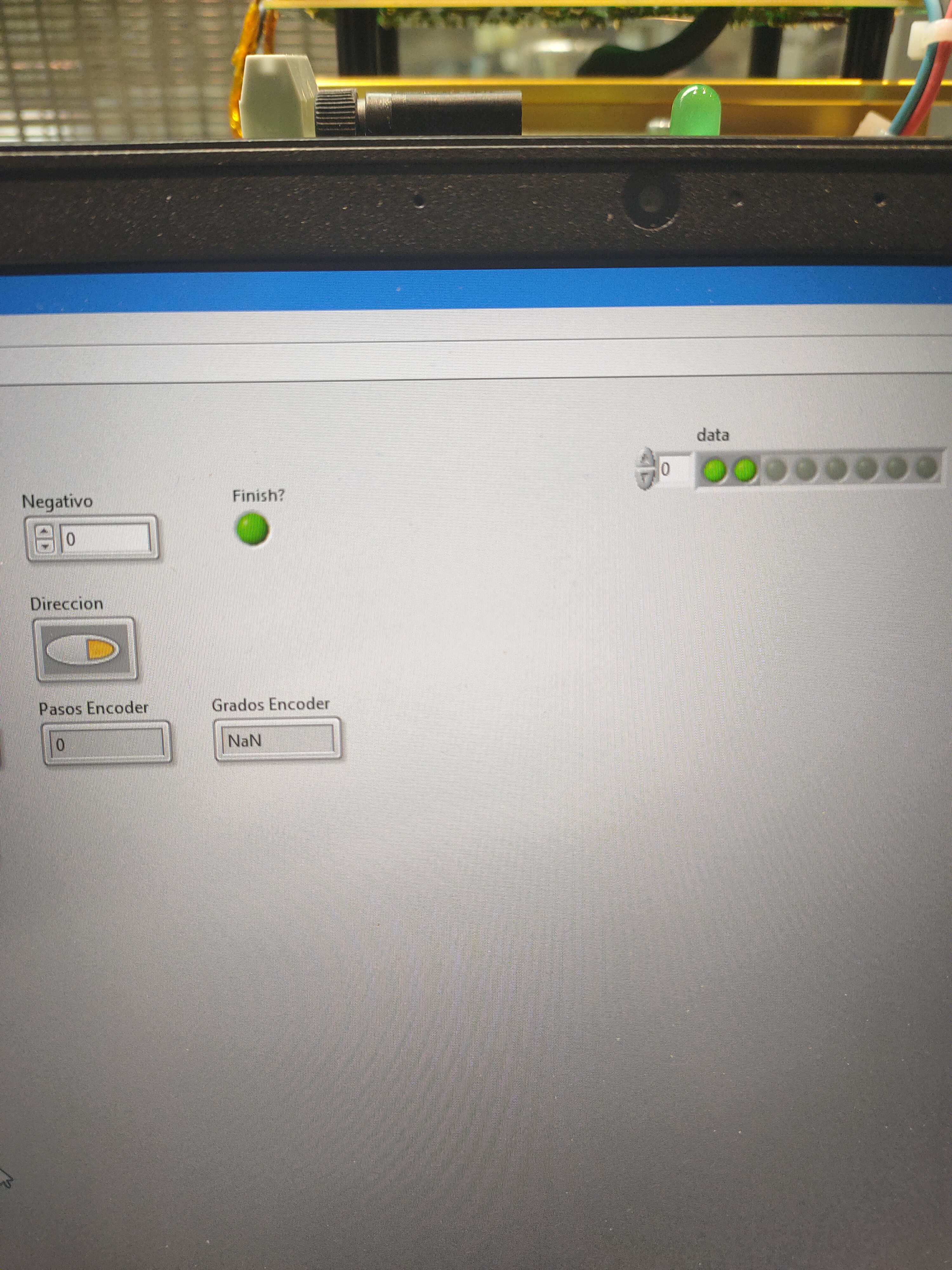
I am controlling a pololu “150:1 Metal Gearmotor 37Dx73L mm 12V with 64 CPR Encoder (Helical Pinion)” by PWM, but when I put the DIR pin HIGH the driver tells me that there is low voltage and it stops working.
I have tried to change the motor terminals and it rotates in both directions when the DIR pin is off.
Can it be due to a short circuit?
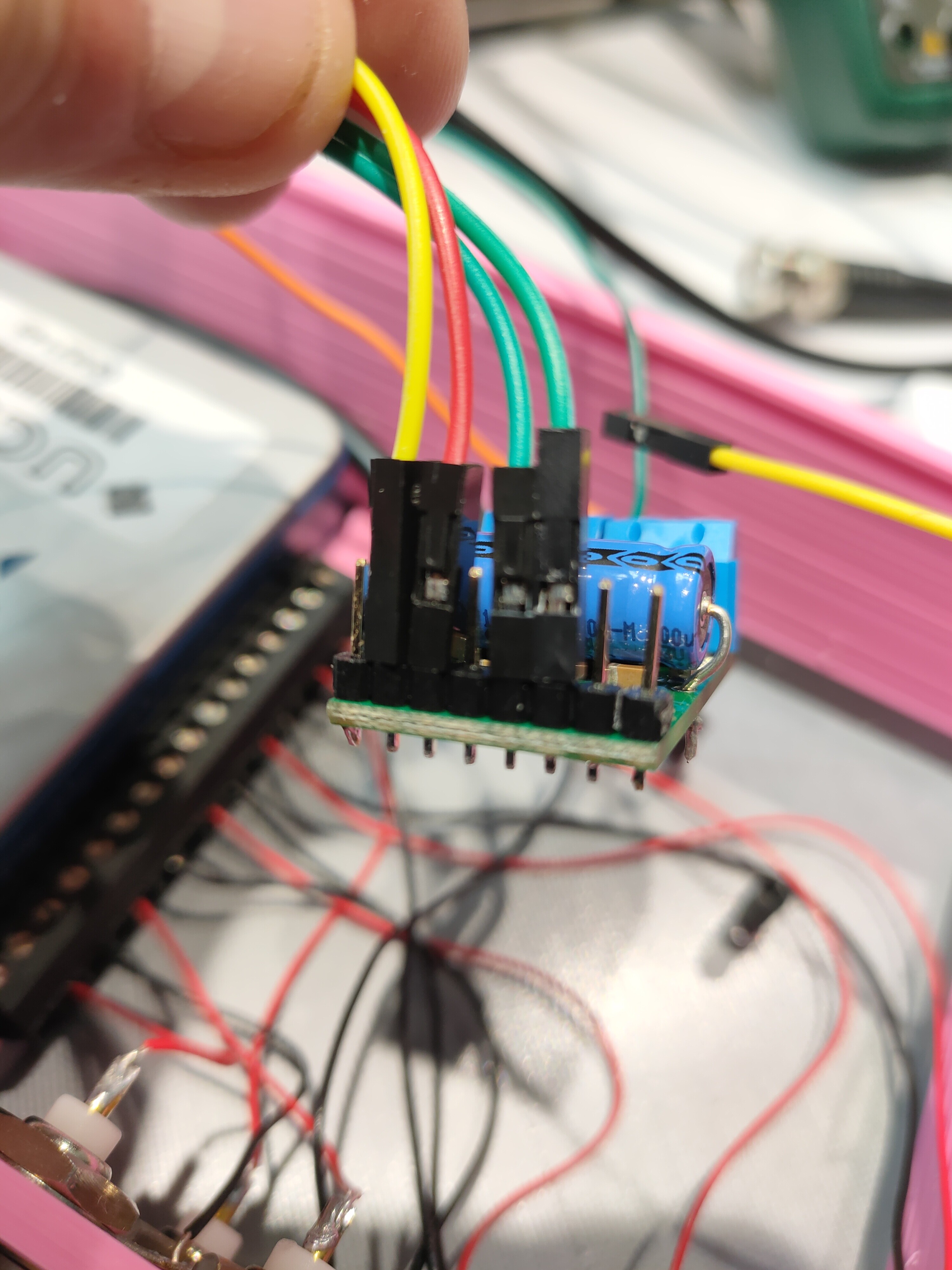
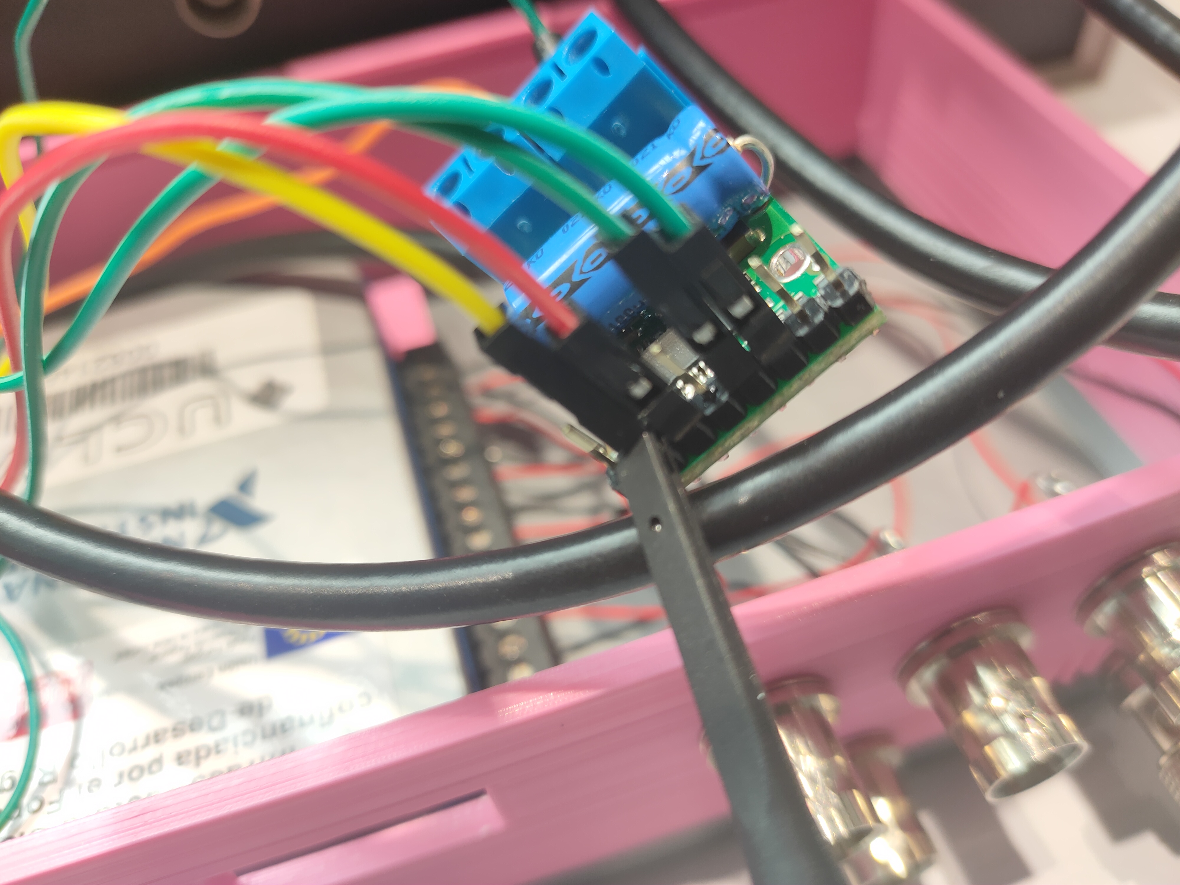
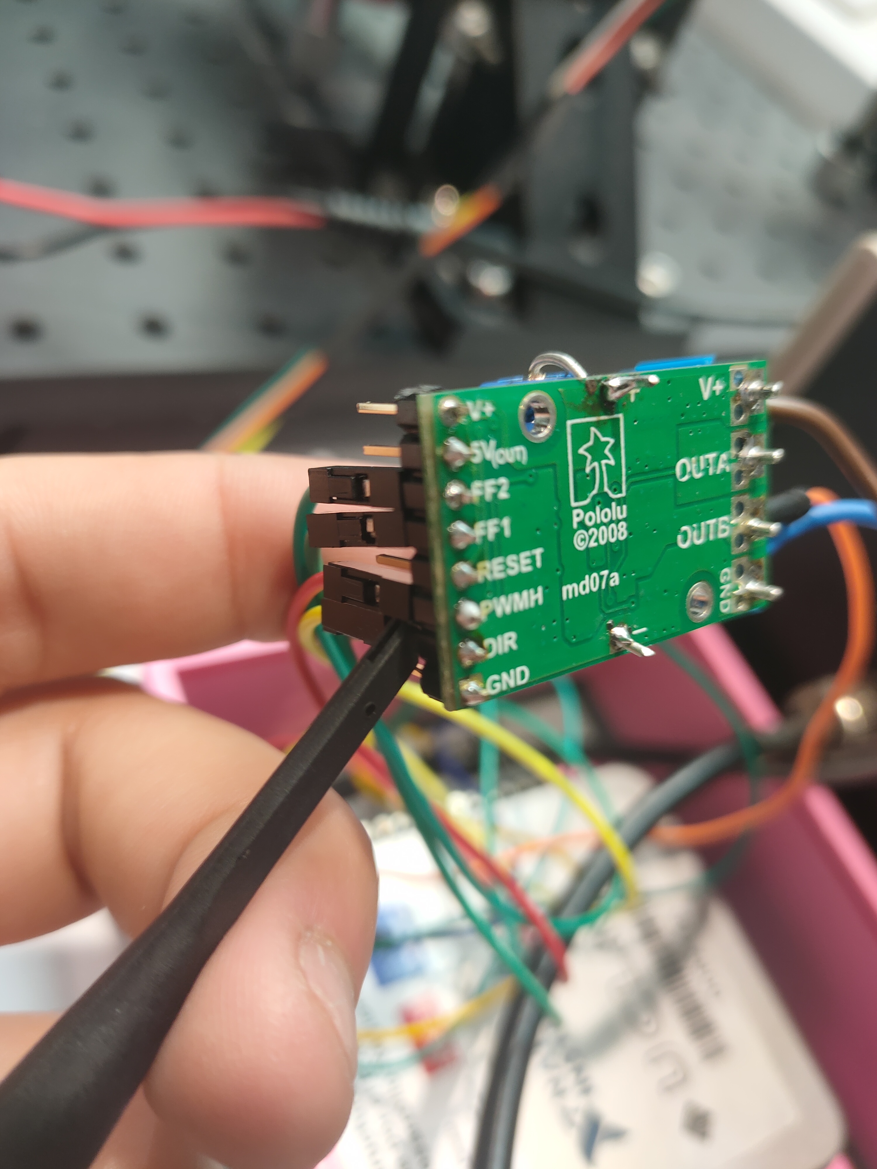
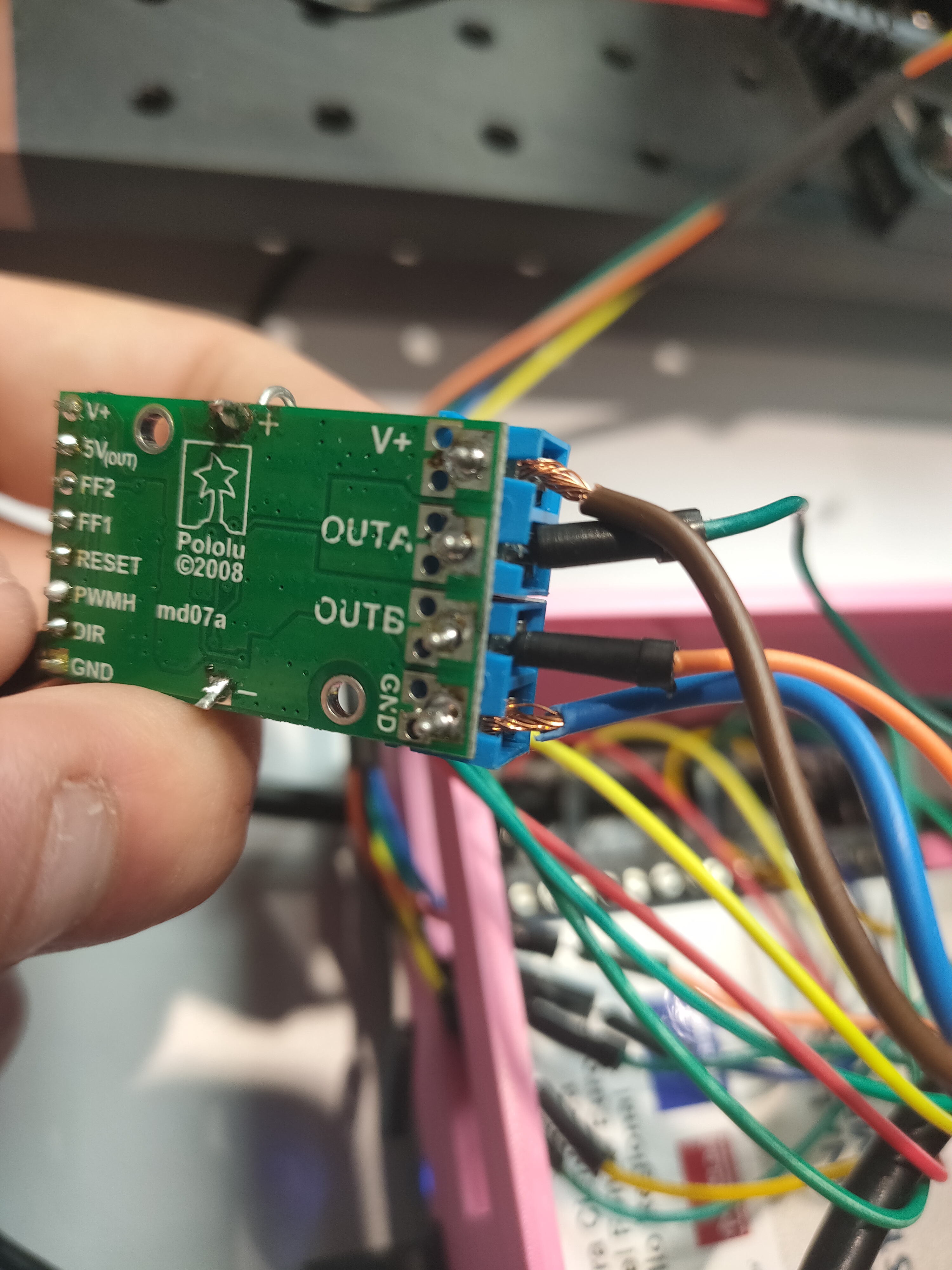
Attached image of the driver and the generated error
Greetings

Hello.
It looks like you do not have a common ground connection with whatever is sending your control signals; that is necessary for your setup to work.
Also, it looks like some of the solder joints on your logic pins and electrolytic capacitor leads might not be fully wetted, so you might try adding just a little bit more solder to those. The Adafruit Guide to Excellent Soldering, might be a useful reference for that. Additionally, I would trim the electrolytic capacitor leads while you are at it; leaving those untrimmed does nothing but create an unnecessary shorting hazard.
If adding the ground connection and improving your solder connections does not resolve the problem, I suggest using a oscilloscope or multimeter to confirm that you are applying the signals you are expecting.
- Patrick
Hello Patrick
I already added more welding at the points you mentioned and the problem persists.
The signal I send is a digital signal from a National Instruments USB 6002 DAQ card and the signal is generated well. I also tried to feed the DIR pin with the 5v provided by the 5VOUT pin of the driver and it still gives the same error.
I want to add that the controller was working perfectly, but I had to disconnect it and reconnect it is when the failures in the DIR pin started
Just to confirm, are you now testing your driver with a ground connection on the logic side, and is it still able to spin the motor in at least one direction? Also, I just noticed that it appears there is not a ground connection on the motor power side of the driver either. Is it possible you ever tried to power the driver and send signals to it without those ground connections? Can you send me some pictures of showing your soldering fixes and how you are currently testing the driver?
Can you monitor your setup with an oscilloscope to see what is going on? In particular, I suspect it would be interesting to see what happens with the DIR signal when you try to set it high.
- Patrick
Good morning Patrick
If I have the logic part grounded, it will run in one direction as long as the DIN pin status is LOW.
I use an adjustable laboratory power supply and connect the V+ and GND as indicated on the driver.
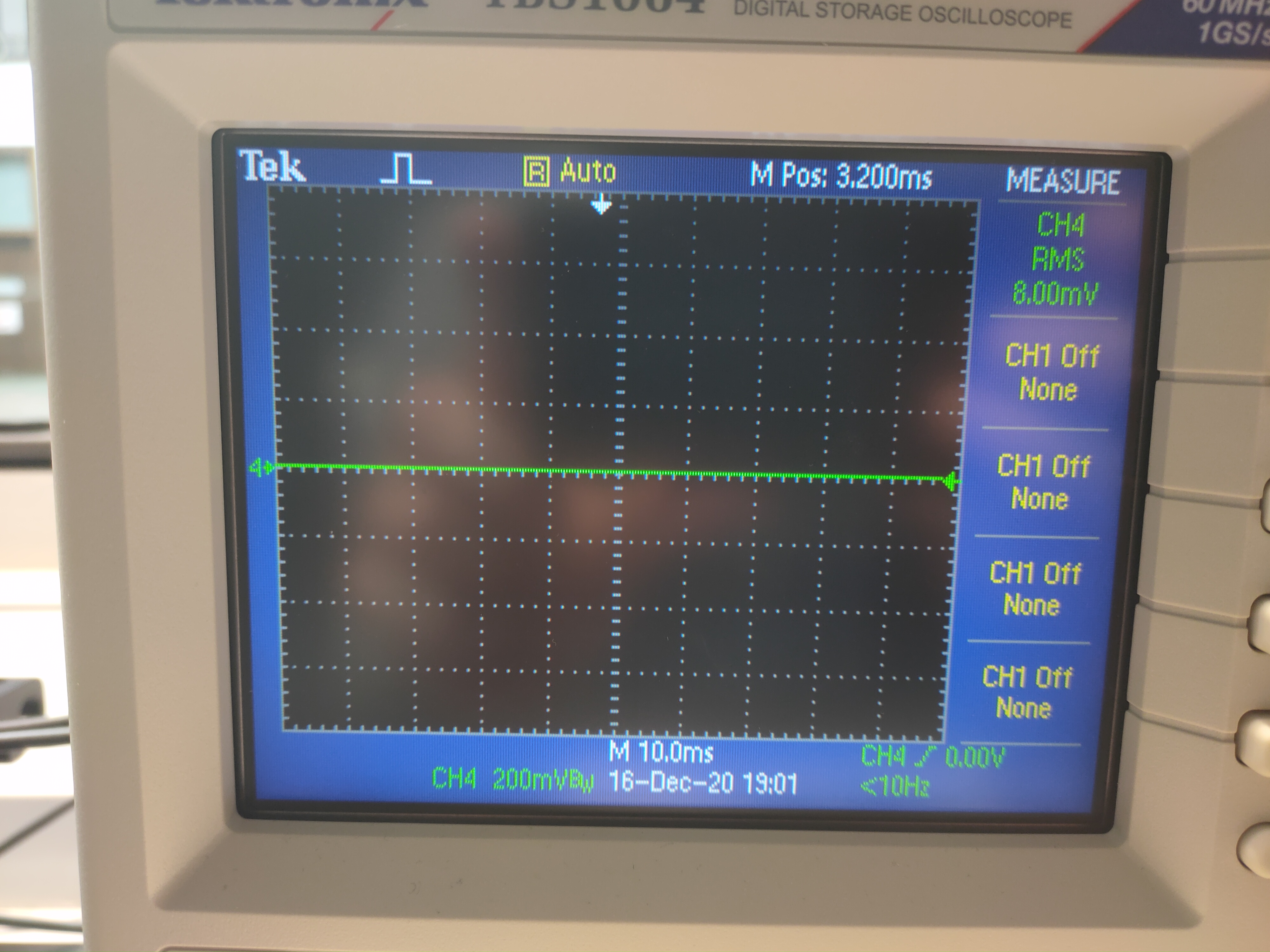
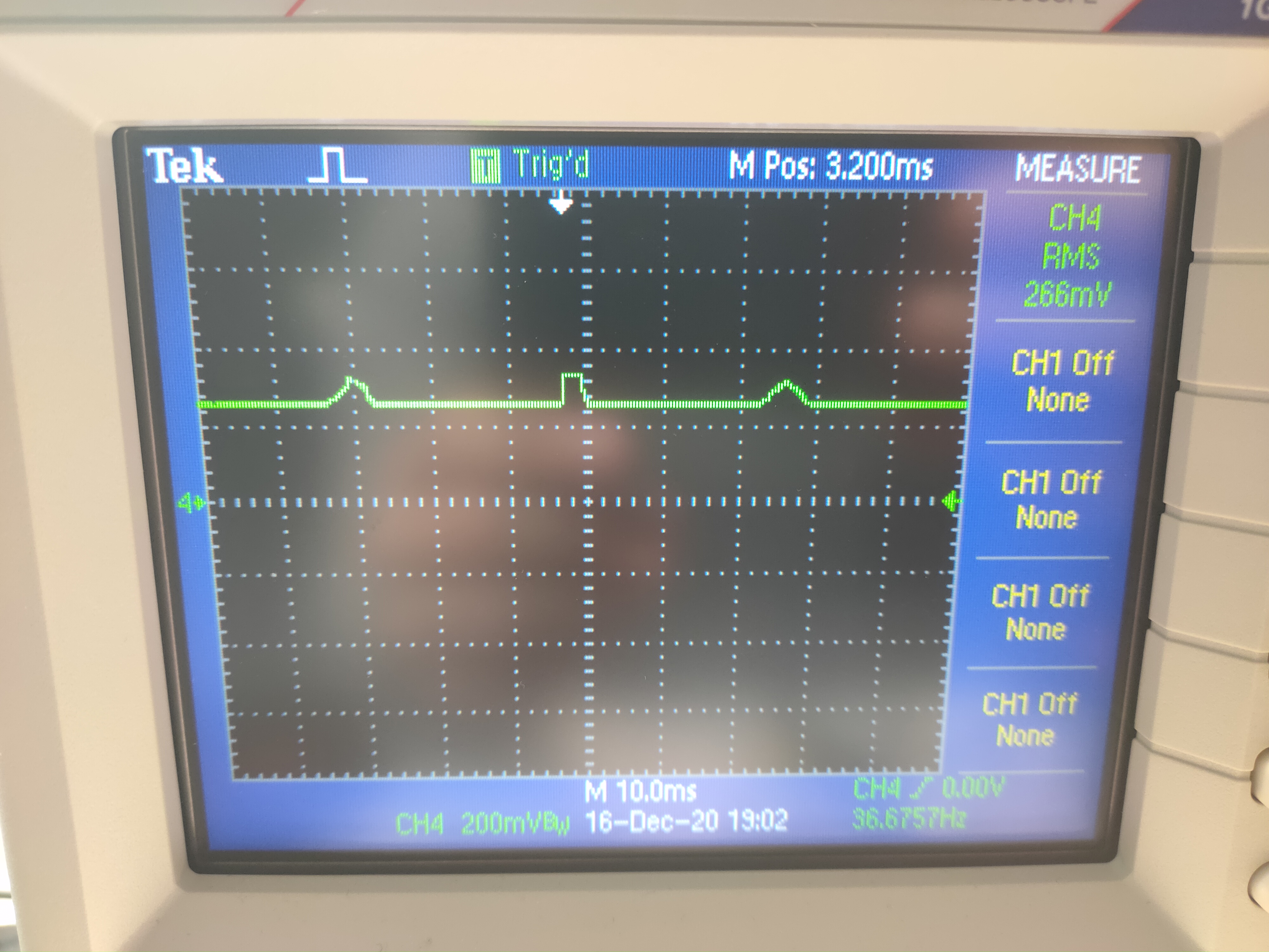
Here is a picture of the DIR behavior
LOW
HIGH
and welding
Victor
Thank you for posting all of those pictures and scope captures. I am concerned that your pictures still do not show anything connected to the GND pin next to your driver’s control pins, so it seems like you might be testing your motor driver without a common GND connection with your controller. As I mentioned before, we expect a common GND to be necessary for your driver to work, and every time you try to use the driver without that connection you risk damaging something.
If you have not already, can you use your scope to monitor the DIR pin when you do have that common GND established? If you see the same behavior then the DIR pin has probably been damaged. If you see different behavior, can you post it?
Also, some of your solder connections, especially the terminal block connections which are a little easier to see now in your last pictures, still do not look great. I would also suggest trimming and tinning the wires connected to the main V+ and GND since the exposed stranded wire is a shorting hazard.
- Patrick