
I am also trying to make my two tb9051’s work. So far they do not. I first used the 3 pins pwm1, pwm2, and en, in the table with both 3.3v and 5v. But I forgot to apply 5v to Vcc since most of your other drivers have internal regulators. I fixed that, and they still don’t work. Could I have fried them somehow?
Hello.
I moved your post into its own thread.
In general, sending control signals to a device while it is not powered is not good practice and has the potential to cause damage. However, there are a few things we can check to be more certain if your board seems okay.
To be clear, we have a few products that use the TB9051FTG, but it sounds like you are using the single motor driver carrier; is that right? What are you using to generate your logic signals? How are you supplying power to VIN? Can you also post pictures that clearly show your connections, including any soldered joints?
-Jon
Here is a picture, but I have already removed them from my robot. I’m pretty sure they are dead so I moved to an alternative option. I never got a pop or sizzle out of them. The ribbon connector went to Teensy 3.5 digital IO pins which run at 3.3 v, and are all PWM able. Power came from a 4s lipo. I first ran a 20,000 pwm signal to EN, as instructed (I verified this on my scope), but later tried the individual PWMs with EN high. Maybe that fried them?
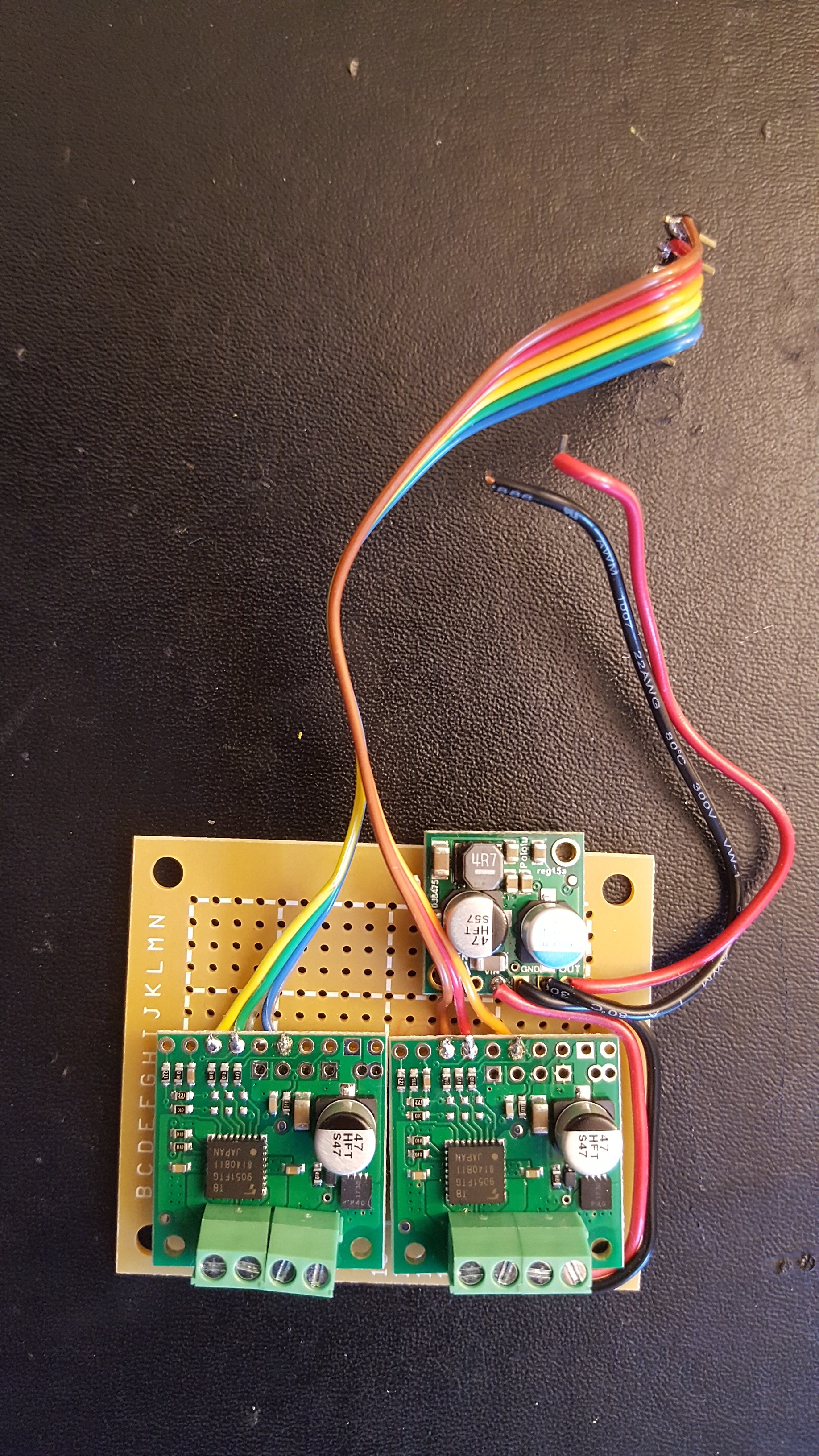
Your soldered joints look like they might not be completely wetting the pads, which would mean that those connections are not continuous and it would explain why your system is not responding. I recommend heating those joints up again to reflow the joint so that they look like the ideal joints shown in this tutorial.
By the way, you should ensure that your components share a common ground. From your pictures it looks like you might already be doing this by connecting the GND terminal on one of your motor drivers to GND on your regulator, which looks like it probably connects to ground on your Teensy. It is not entirely clear if the other motor driver is also connected to ground through your perf board, but, in general, it does not hurt to make additional ground connections, and we make available several GND pins to connect to on those motor drivers.
-Jon
The grounds are all common with the battery negative. I always test my solder joints with an ohm meter, and they are good. But I will reheat as suggested.
It just noticed that neither driver is connected to ENB, which is an inverted enable pin. It is connected HIGH by default, which disables the driver. So, you should pull ENB to GND on each board to enable them.
-Jon
That was the problem! Thanks it works now. Sorry I did not read the docs more closely.
1 Like