I have two TB67S279FTG Stepper Motor Driver Carrier - Full Breakout modules, using these with an Arduino Uno R3. I have taken care that the power supplies to motor and Arduino have a common ground. I checked resistance across the terminals on the modules for each motor coil, finding 7-9 ohms each. I’ve tried this with two motors, S20STH30-0604A Pololu #1204, NEMA 8. The coil wires are very fine on these so they were soldered to a short length of 24AWG wire to give a solid connection under the terminals. I made certain the A & B coils were properly identified. ). I set VREF to 0.48 V, since these are 0.6 A motors. The motor power supply is 12.2V (measured across VIN, GND), without a capacitor, as depicted in the Pololu documentation. I use a DC-DC buck to step this motor supply voltage down to 7V, supplying Vin and the power ground on the Arduino, and verified that the grounds on both sides of the buck are common to within 1 ohm…
I never been able to get these units to move stepper motors. I have verified voltages = VCC at ENABLE, DIR, DMODE0, DMODE2, and GND is connected to the logic power supply. The ARDUINO STEP output looks fine (+5V…0V pulses at desired frequency) on the oscilloscope, probing at the STEP terminal, but I get no stepping.on either motor. I ramp the step rate from the Arduino from near 0 to 4.8 kHz over 3 seconds, then hold it at 4.8 kHz, DMODE0…2 set for 1/8 microstepping. I tried two motors, neither moved, they should have rotated 3 times per second.
One module exhibits different behavior: It indicates “Detected motor load open (OPD)”. After reading the fault condition (LO1 at VCC, LO2 low) I have de-powered the driver module, which should release the error detection status according to the Toshiba documentation for TB67S249FTG, p. 11. It always returns on power-up, and does with with both motors, no such fault was observed on the other module… The motor load open error makes no sense to me when the load is clearly discernible on the terminals of the module. I visually rechecked the solder connection to the header pins, all looked okay. On this module the STEP inputs are severely attenuated after I connect them to the STEP input (They are fine coming from the Arduino when unconnected).
Many hours have been spent fruitlessly on a couple of $13 components, hardly a great return. I had no such troubles with the DRV8824 or A4988.
Hello.
I am sorry to hear you are having trouble with your drivers. Can you clarify what drivers you are using? You mentioned the TB67S249FTG in the thread title, but then in your post you mentioned both that driver and the TB67S279FTG. That is important to figure out first since the VREF current limiting equations for the two boards are different. If you are not sure which board you have, you can check the labels on the main IC.
Can you post some pictures of your setup that show all of your connections, including close-up pictures of both drivers? Also, what are you using for your main power supply, and have you tried looking at the motor driver outputs with your scope? Scope captures showing the behavior of those might be helpful.
- Patrick
Hi Patrick
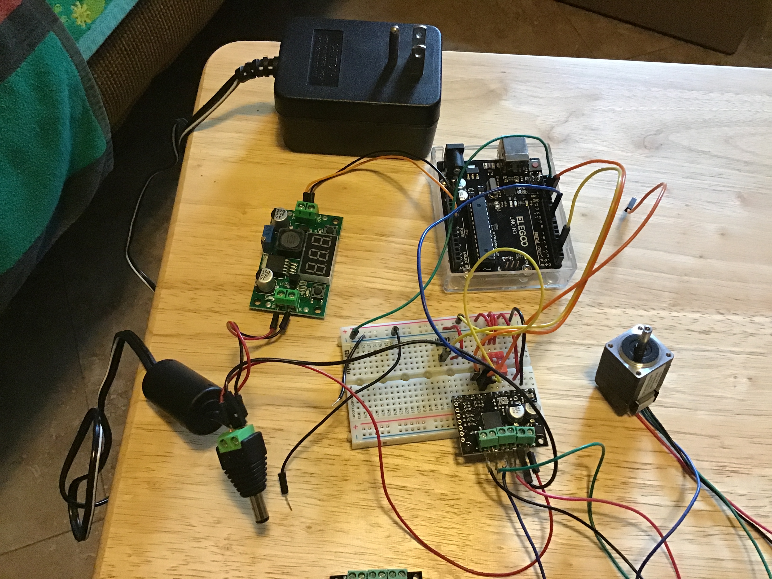
You are right, the VREF values are indeed different. I’m using 249 (lower current), not 279, I miscopied. Here’s the setup in a photo. Only one driver module attached, a generic (grounded) 12V 1.25A wall wart as power supply with a step-down DC-DC transformer for the Uno R3 since the Elegoo (or genuine Arduino, for that matter) isn’t very happy with 12V on Vin regardless of what the docs on R3 say about max 20V input. I tried it again with a 12 V 2A supply, no difference. As I mentioned, I verified a common ground, having some appreciation for what ground loops can do to mess things up.
With things powered up, the lower trace is the STEP input, the upper is across one of the coils (the other looks just the same). Just +/- 500 mV spikes on the STEP transitions. Sorry, this scope doesn’t do screen capture. The motor isn’t even humming, but the shaft doesn’t turn quite as readily as it would with nothing.
After spending about 6-8 hours, my labor costs have vastly exceeded the hardware outlay. I know Toshiba makes good stuff but this driver has been a waste; I have a couple others of different types on order.
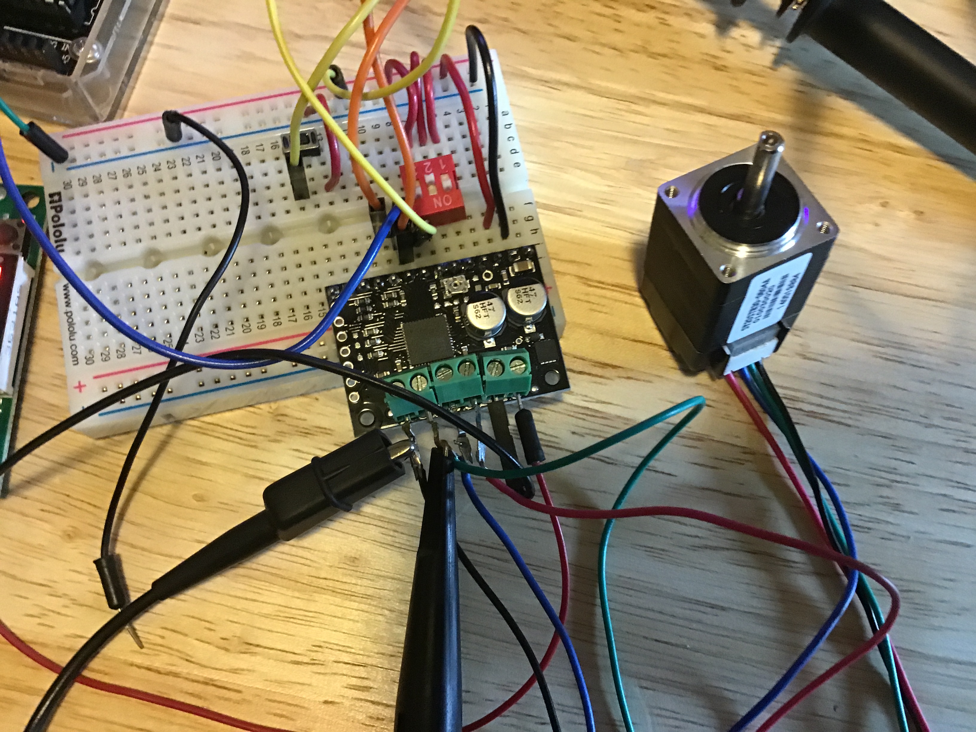
Here’s a driver close-up. The momentary switch to ground (yellow lead, the leftmost red wire should be black, it’s is actually ground, not VCC, I changed something recently) is for the user to trigger an interrupt on the Uno.
I’m out of ideas on this, after triple checking most everything.
Tim.
Hello, Tim.
It looks like you have the ground clip of your oscilloscope connected to one of the driver outputs; that should never be connected to anything besides ground. Connecting the ground clip to a motor output could damage your probe or scope. To measure motor outputs, two scope channels should be used with the each probe connected to one motor output pin and both ground clips connected to the driver’s ground.
Aside from that, I do not see any obvious problems with your setup. We test all of these boards, so they were likely working at some point, and it seems very unlucky for you to have received two problematic boards. Just to clarify, which driver do you currently have in your setup (i.e. is it the one that is triggering the OPD error)? Could you measure the VCC pin on the board to make sure it is receiving power? Also, could you post close-up pictures of both sides of each board with an indication of which one is which?
Brandon