Hello,
I would like kindly ask you for help regarding TB67S249 (Compact Carrier).
I use this driver with 2A NEMA23 motor, 24V VDD and I have a problem when I tryed to set higher current than aproximatelly 1A (= VREF more than 0,8V). The Driver is not able to enable and doesn’t run properly.
I use 1/8 step = DMODE 0 and DMODE 2 is high. The DMODE setup is setted by jumpers and is not settable as MCU output = I can’t set standby mode on DMODE pins.
When I switched the driver on (VDD = 24V) and activate enable pin with current setup > about 1A, the driver is not working (it looks that it is in some fault mode…).
If I reduce the current to 0,8A, the driver is working after motor enable activation and is running properly.
Is there any protection or a idea, why I’m not able to use current > 1A?
Can you post some pictures of your board and setup that show all of your connections? Can you also tell me what you are using to power and send signals to your stepper motor driver? Posting a datasheet for your motor might also be useful.
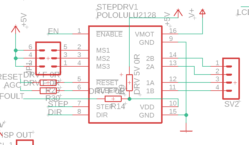
It is universal schematic for A4988 etc.
Used Power connection is 24V/2A power source to VMOT. PIN 10 is used as foult output from driver to MCU.
DMODE0, 1, and 2 are setted by jumpers.
Step and Dir, Enabled, reset and AGC are connected directly to MCU output (5V logic)
If I set 0,6A, motor is working properly
If I set 0,8A, motor is working only sometimes.
If I set 1A, it is not possible to enable the driver
Interesting is, that If I set 0,8A and I run the motor and the motor looses steps (mechanical collision of moved parts), it sometimes automatically disable the motor.
It looks, that there is some protection against high current. I need to set around 1,25A - this current is ok for my application, but I cant :-/ I fon!t check Foult output, I think that there will be some error flag, but I need to use the driver as a replacement of A4988 or similar drivers and I had a good experiences with old toshiba drivers… Maybee is this driver to clever
That schematic makes it look like you might be driving or pulling the nFAULT pin high. The board includes a series resistor which makes this safe to do, as in the case where you are using it in a circuit designed for the A988 (which expects a logic supply on that pin), but you will not be able to read the driver’s fault output if you do that. As described in the [product page description] under the “Control inputs and status outputs” header, nFAULT is pulled high on the board by default, so all you should do to use it as a fault signal is read the pin (i.e. disconnect it from any voltage supply and only connect it to an input pin on your controller) to see if it goes low.
After correcting how nFAULT is connected, can you also confirm whether it goes low whenever the driver stops working? I also suggest using an oscilloscope to see what is going on. Specifically, I recommend looking at your power supply line, then looking at your logic signals to confirm they are doing what you expect.
Can you also post some pictures of your physical setup (not just a schematic)? The driver’s ability to handle higher currents can be affected by the quality of your connections and how well the space around the board facilitates air circulation, so it would be useful to see how things are actually connected in your system.
Hi Patric, maybee I found the problem… I installed a shotky diode between 24V source and driver VMOT pin in old revision of PCB. After I change this diode by a wire (:-)), the driver start working properly = it looks, that there is some input voltage controll system- I will test this setup today and let you know…
The pull up resistor on foult pin (as you wrote) is not installed on PCB, it is universal PCB where I can use A4988 (5V needed) or use this pin as Foult on TB67Sxxx. I use 0R resistor as a jumper for setup. In my setup is this pin connected to MCU input and not to 5V or to pullup resistor.
this is the right old schematic with diode (the diode is removed now):
Partick, can you shortly describe me the needed steps for driver activation? I think if my steps are OK, or is there some NOK step from your point of view: