TB67S128FTG Current Limiting Not Working

I’ve recently purchased a TB67S128FTG. I’ve soldered all of the pins and I currently want to set the current limit for the driver to drive this stepper motor. According my my calculations, the Vref I should the for the driver should be as follows:
Vref = 1.68/1.56 = ~1.0769V (if someone could confirm this is correct for me, that would be great).

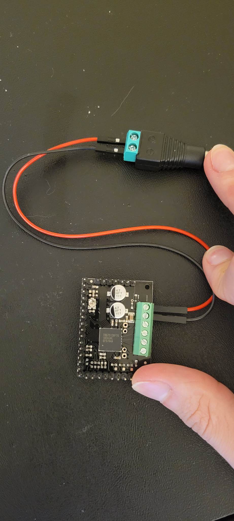
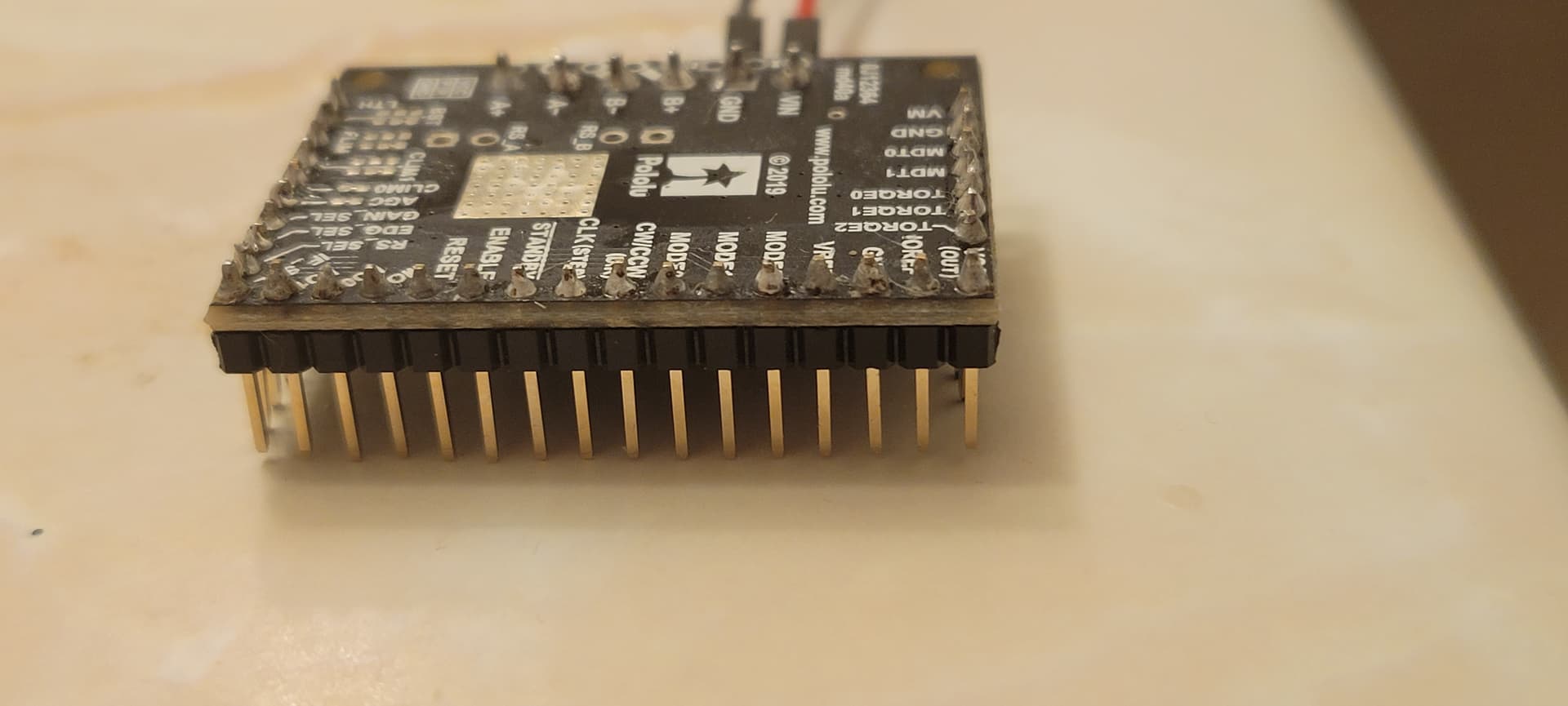
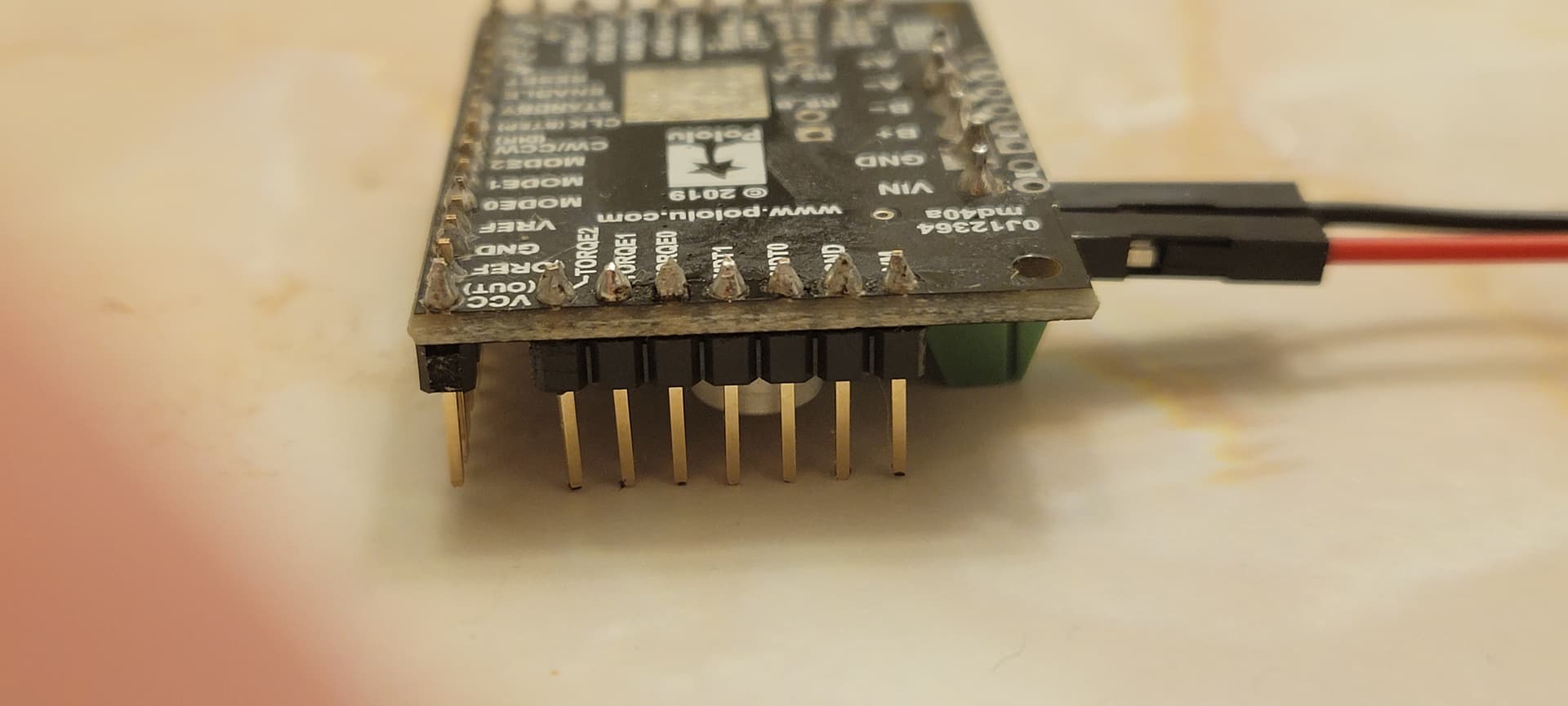
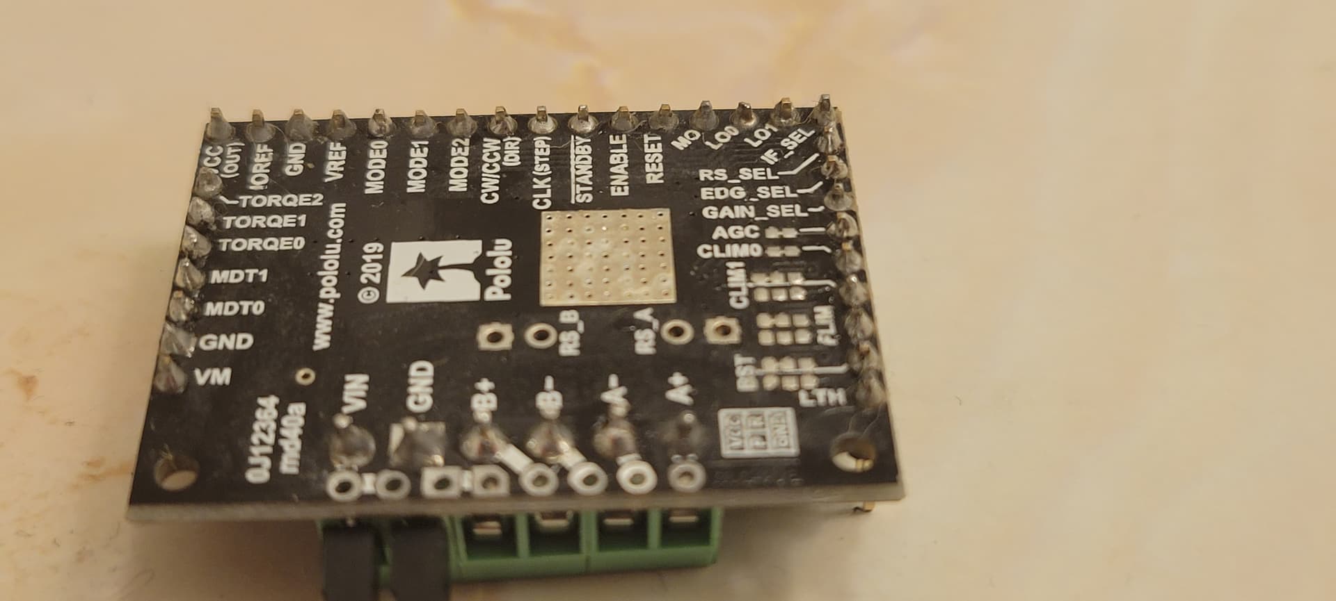
I’m trying to follow the tutorial shown at Video: Setting the Current Limit on Pololu Stepper Motor Driver Carriers, however, I’m not getting a reading on my multimeter. My multimeter is in the same mode as the one used in the video (see attached photo). I’m not sure what I’m doing wrong. I have the red end of my multimeter touching the potentiometer and the black end touching the ground pin of the driver. Even after I turn the pot, there is still no reading on the multimeter. I even tried connecting the driver to my Raspberry Pi controller (even though I don’t see why that would make a difference) but still, no reading. Pictures are attached to aid my description of the problem.


Hello.

Your target VREF value seems fine for the TB67S128FTG and the motor you linked to.

Can you post a picture of the bottom side of the board so I can inspect the soldering? What are you using to power your driver, and have you confirmed the right voltage is reaching the driver’s VIN and GND pins with your multimeter? If you have not already, I suggest you also try measuring the voltage at the VREF pin (instead of the top of the potentiometer) and at the VCC pin on the left side of the board.

- Patrick


Hi Patrick. I’ve attached images at multiple angles so you can get a good look of the soldering.


I’ve also attached an image containing the specs of my power supply that I’m using to try and power the driver.

have you confirmed the right voltage is reaching the driver’s VIN and GND pins with your multimeter?

Sorry I’m a newbie. Are you saying to put the black probe on GND and red on VIN to see if the multimeter outputs a nonzero value?

If you have not already, I suggest you also try measuring the voltage at the VREF pin (instead of the top of the potentiometer) and at the VCC pin on the left side of the board.

I did try black probe of multimeter on GND and red on VREF pin and I experienced the same behavior that is described in the original post. Are you saying I should instead try black probe on GND and red on VCC?

EDIT:
After trying to above troubleshooting, I’ve gathered the following results with the multimeter in the same mode shown in the attached image in my previous reply:

Black Probe: GND (power source side), Red Probe: Vin, Voltage Reading: ~11
Black Probe: GND (power source side), Red Probe: VCC (out), Voltage Reading: ~4
Black Probe: GND (power source side), Red Probe: Vref, Voltage Reading: 0
Black Probe: GND (adjacent to Vref), Red Probe: Vref, Voltage Reading: 0
Black Probe: GND (adjacent to Vref), Red Probe: VCC, Voltage Reading: ~4

I then tried making many, many clockwise turns on the potentiometer and tried to get a reading again with the black probe on GND (either one) and red probe on Vref. Now I can get a reading between 1 and 3. However, after just a slight turn in either direction on the pot, measuring again yields a reading of 0.

Hopefully, this information is helpful. I also notice my multimeter always outputs an integer value, whereas the one used in the tutorial video outputs a much more fine-grained decimal value. Is this indicative of my multimeter being lower quality perhaps?

I’ve captured the behavior described in my last reply in a video recording here: 20230117_001117.mp4 - Google Drive

As seen, I have the red probe clipped to the screwdriver that’s turning the pot and the black probe clipped onto the GND pin.

Unfortunately, it looks like the current limiting potentiometer has probably been damaged. I can see you turn it all the way around several times in the video, but there should be a small end stop that limits the range to less than a full rotation. If you email us with your order information and a reference to this thread, we should be able to help you out with a replacement.

Separately, it looks like you might have a few cold joints among your solder connections. I suggest using this as an opportunity to learn how to fix that so you can avoid it on future boards. The Adafruit Guide to Excellent Soldering is a good reference for soldering advice and shows some examples of cold joints in the “Common Soldering Problems” section.

By the way, anytime we are asking what the voltage is on a pin in a DC circuit like this, we are almost always asking what the voltage (i.e. the electrical potential) is relative to GND, which means the black probe will be on GND and the red probe will be at the other point. If someone is looking for the voltage relative to something else, they generally should be specifying both points.

- Patrick

Thank you so much for your response, Patrick. I’ve sent the email. I appreciate all of the advice!